


Until recently all existing virtual lab solutions were based on vendor appliances provided as virtual machines. Such an approach allowed us to emulate closely the real HW (some of those appliances had virtualized data planes as well - e.g. vEX, vMX). However this is not always the desired case. Sometimes we just want to check routing, some protocol behavior or other control plane features implemented on vendor appliances (to see the difference between management, control and user plane see Management vs. Control vs. Data Planes in a Network Device). In such scenarios the VM approach can be overkill. It is heavy in terms of memory and CPU and ZTP features are lacking (some vendors do not support ZTP on virtual appliances). In such cases one can use containers instead of VMs. Let’s take a look at the latest addition to virtual lab software, Containerlab ![]() .
.
Installation prerequisites are pretty straightforward: Linux / Windows / MAC OS (x86) (Windows users will need to install WSL on their machines) with Docker preinstalled. All other dependencies are handled during installation. After that step, immediately there will be two major differences visible between VM-based projects and Containerlab:
- No UI - all configuration (appliances, connections) is handled by a simple YAML file - however this makes automation a breeze,
- Concentrated on containers - however VMs are still fully supported by launching them inside a container,
- ZTP - all supported vendors
 have ZTP supported natively. All you need to do is to reference the config file within the YAML formatted lab definition or mount them directly in the container.
Example usage
Let’s now look at an example on how one can use Containerlab to build a network topology. In the following sections we will show what a config YAML file looks like, how to choose and prepare images (FRR in our example), how to structure the files into correct directories, and how to deploy the lab. Finally we will check if everything works as expected.
Example topology
To show how easy it is to use the Containerlab project, let's create a simple topology with it like the one in the diagram below:
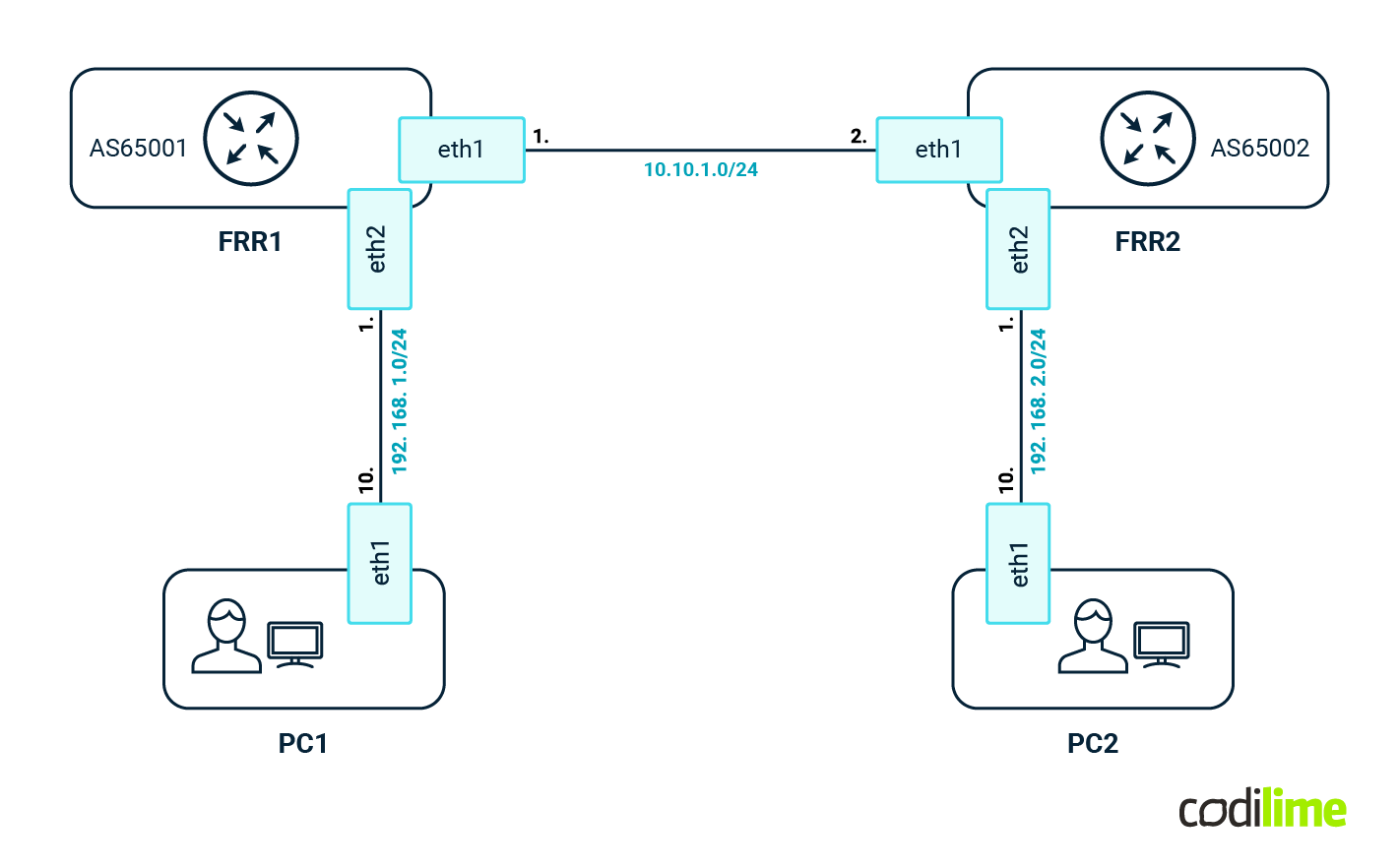
As a first step, we need to define the topology:
# cat blog.clab.yml
name: blog


topology:
 nodes:
   frr1:
     kind: linux
     image: quay.io/frrouting/frr:9.1.0
     binds:
        - config/frr1/daemons:/etc/frr/daemons
        - config/frr1/frr.conf:/etc/frr/frr.conf
   frr2:
     kind: linux
     image: quay.io/frrouting/frr:9.1.0
     binds:
        - config/frr2/daemons:/etc/frr/daemons
        - config/frr2/frr.conf:/etc/frr/frr.conf
   PC1:
     kind: linux
     image: praqma/network-multitool:latest
     exec:
        - ip addr add 192.168.1.10/24 dev eth1
        - ip route add 192.168.0.0/16 via 192.168.1.1
        - ip route add 10.0.0.0/8 via 192.168.1.1
   PC2:
     kind: linux
     image: praqma/network-multitool:latest
     exec:
        - ip addr add 192.168.2.10/24 dev eth1
        - ip route add 192.168.0.0/16 via 192.168.2.1
        - ip route add 10.0.0.0/8 via 192.168.2.1
 links:
   - endpoints: \["frr1:eth1", "frr2:eth1"]
   - endpoints: \["PC1:eth1", "frr1:eth2"]
   - endpoints: \["PC2:eth1", "frr2:eth2"]
Above we can see the definition of the nodes - we will use FRR container images ![]() as well as Linux to emulate the endpoints. As you can see, almost any Docker image can be used here. At the bottom there are links defined between FRRs and PCs (those are veth interfaces, so all communication is kept in the kernel, which is way faster than GNS3 or the EVE-NG approach). Each FRR comes with its own simple configuration:
as well as Linux to emulate the endpoints. As you can see, almost any Docker image can be used here. At the bottom there are links defined between FRRs and PCs (those are veth interfaces, so all communication is kept in the kernel, which is way faster than GNS3 or the EVE-NG approach). Each FRR comes with its own simple configuration:
FRR1
# cat config/frr1/frr.conf
frr version 9.1_git
frr defaults traditional
hostname frr1
no ipv6 forwarding
!
interface eth1
ip address 10.10.1.1/30
exit
!
interface eth2
ip address 192.168.1.1/24
exit
!
interface lo
ip address 10.2.0.1/32
exit
!
router bgp 65001
no bgp ebgp-requires-policy
neighbor 10.10.1.2 remote-as 65002
!
address-family ipv4 unicast
 network 10.2.0.1/32
 network 192.168.1.0/24
exit-address-family
exit
!
end
FRR2
# cat config/frr2/frr.conf
frr version 9.1_git
frr defaults traditional
hostname frr2
no ipv6 forwarding
!
interface eth1
ip address 10.10.1.2/30
exit
!
interface eth2
ip address 192.168.2.1/24
exit
!
interface lo
ip address 10.2.0.2/32
exit
!
router bgp 65002
no bgp ebgp-requires-policy
neighbor 10.10.1.1 remote-as 65001
!
address-family ipv4 unicast
 network 10.2.0.2/32
 network 192.168.2.0/24
exit-address-family
exit
!
end
FRR1 and FRR2
In the YAML file we are also referencing the config/frr1/daemons file (both FRRs use the same config here):
# cat config/frr1/daemons
zebra=yes
bgpd=yes
ospfd=no
ospf6d=no
ripd=no
ripngd=no
isisd=no
pimd=no
ldpd=yes
nhrpd=no
eigrpd=no
babeld=no
sharpd=no
staticd=no
pbrd=no
bfdd=no
fabricd=no


vtysh_enable=yes
zebra_options=" -s 90000000 --daemon -A 127.0.0.1"
bgpd_options="   --daemon -A 127.0.0.1"
ospfd_options="  --daemon -A 127.0.0.1"
ospf6d_options=" --daemon -A ::1"
ripd_options="   --daemon -A 127.0.0.1"
ripngd_options=" --daemon -A ::1"
isisd_options="  --daemon -A 127.0.0.1"
pimd_options="  --daemon -A 127.0.0.1"
ldpd_options="  --daemon -A 127.0.0.1"
nhrpd_options="  --daemon -A 127.0.0.1"
eigrpd_options="  --daemon -A 127.0.0.1"
babeld_options="  --daemon -A 127.0.0.1"
sharpd_options="  --daemon -A 127.0.0.1"
staticd_options="  --daemon -A 127.0.0.1"
pbrd_options="  --daemon -A 127.0.0.1"
bfdd_options="  --daemon -A 127.0.0.1"
fabricd_options="  --daemon -A 127.0.0.1"
With all of those files in place the directory and files structure should look like this:
# tree
.

├── config
│   ├── frr1
│   │   ├── daemons
│   │   └── frr.conf
│   └── frr2
│       ├── daemons
│       └── frr.conf
└── blog.clab.yml


4 directories, 5 files
Now the last step - deploy the newly created topology. We need to execute a single command in the top level directory of our lab:
# containerlab deploy
INFO[0000] Containerlab v0.48.4 started
INFO[0000] Parsing & checking topology file: sonic.clab.yml
INFO[0000] Creating docker network: Name="clab", IPv4Subnet="172.20.20.0/24", IPv6Subnet="2001:172:20:20::/64", MTU='ל'
INFO[0000] Creating lab directory: /[...]/clab-blog
INFO[0000] Creating container: "frr2"
INFO[0000] Creating container: "frr1"
INFO[0000] Creating container: "PC2"
INFO[0000] Creating container: "PC1"
INFO[0000] Creating link: PC2:eth1 <--> frr2:eth2
INFO[0000] Creating link: frr1:eth1 <--> frr2:eth1
INFO[0001] Creating link: PC1:eth1 <--> frr1:eth2
[...]
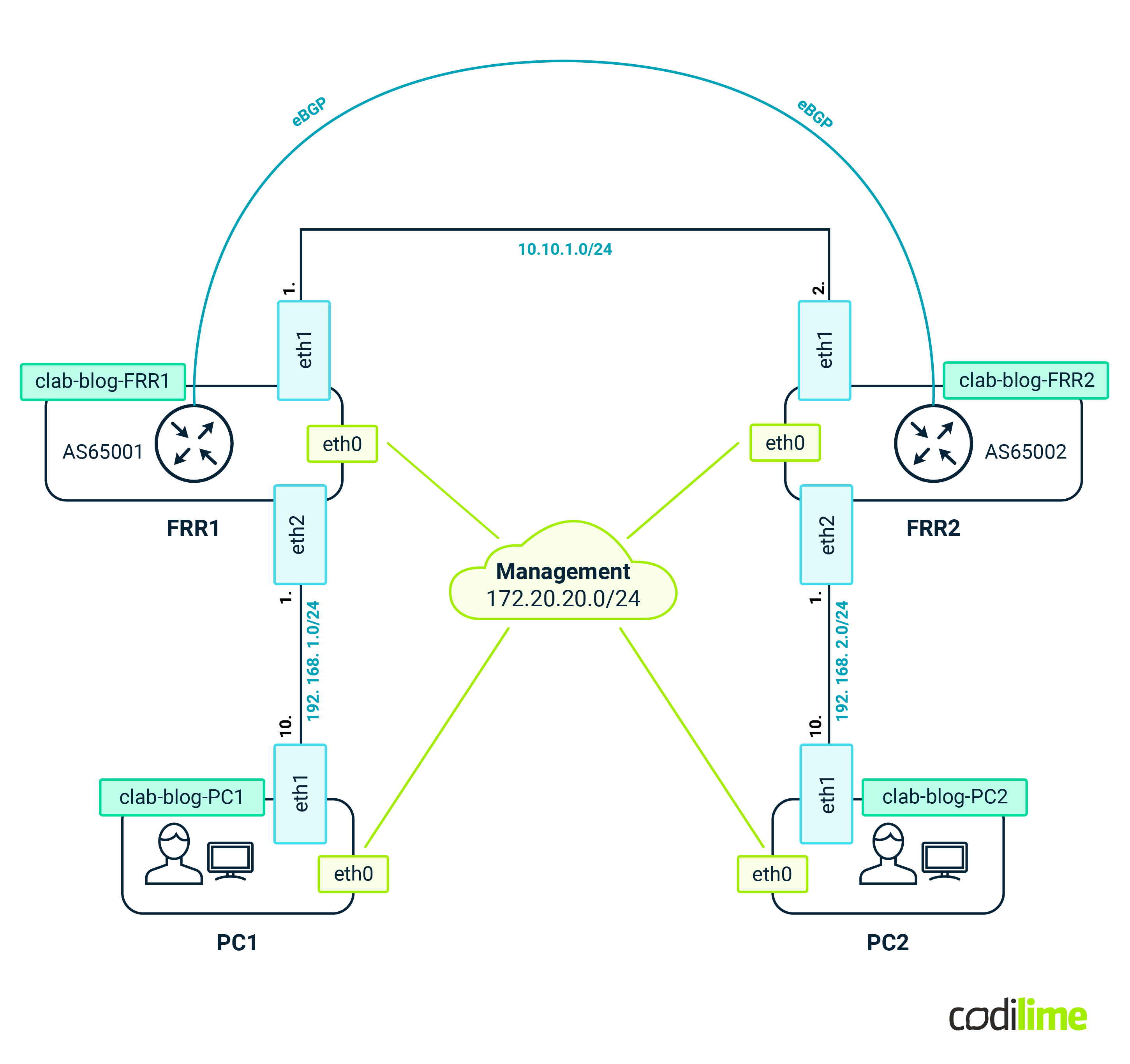
If everything went fine, we should now have a running lab that looks like this:
We can quickly verify if everything is working as intended. Let's check the BGP session between FRR1 and FRR2:
# docker exec -it clab-blog-frr1 vtysh -c "show bgp summary"
\\\[...]
IPv4 Unicast Summary (VRF default):
BGP router identifier 10.2.0.1, local AS number 65001 vrf-id 0
BGP table version 4
RIB entries 7, using 672 bytes of memory
Peers 1, using 13 KiB of memory


Neighbor    V    AS    MsgRcvd    MsgSent    TblVer    InQ    OutQ    Up/Down    State/PfxRcd    PfxSnt    Desc
10.10.1.2   4    65002     6      7          4         0      0       00:01:53   2               4         N/A
Total number of neighbors 1
… so with the BGP session UP, communication between PC1 and PC2 should be possible:
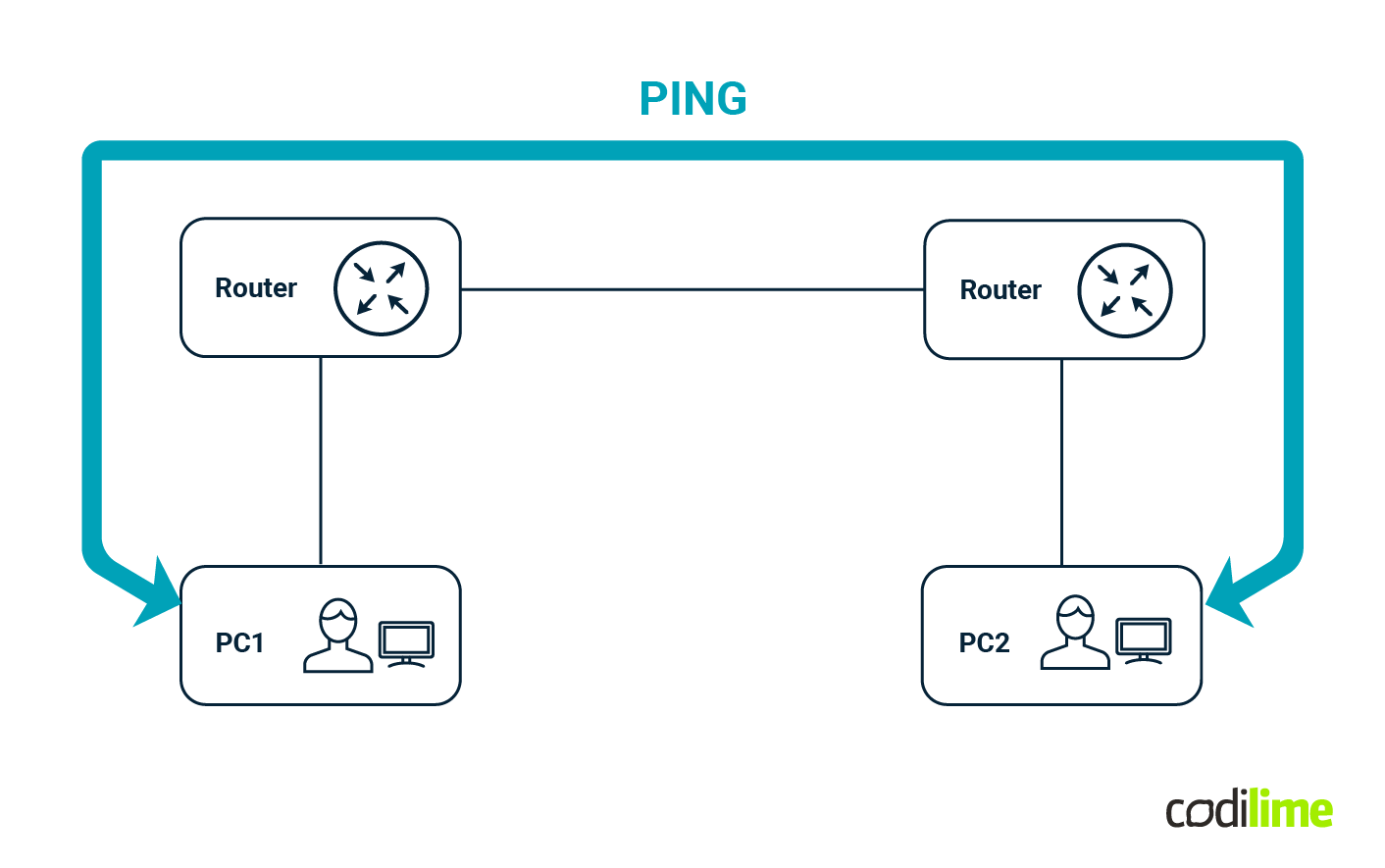
# docker exec -it clab-blog-PC1 ping -c 4 192.168.2.10
PING 192.168.2.10 (192.168.2.10) 56(84) bytes of data.
64 bytes from 192.168.2.10: icmp_seq=1 ttl=62 time=0.093 ms
64 bytes from 192.168.2.10: icmp_seq=2 ttl=62 time=0.087 ms
64 bytes from 192.168.2.10: icmp_seq=3 ttl=62 time=0.123 ms
64 bytes from 192.168.2.10: icmp_seq=4 ttl=62 time=0.086 ms


--- 192.168.2.10 ping statistics ---
4 packets transmitted, 4 received, 0% packet loss, time 3046ms
rtt min/avg/max/mdev = 0.086/0.097/0.123/0.015 ms
And indeed this is the case.
The last thing left for us to check is memory consumption:
# docker stats
CONTAINER ID   NAME         	CPU % 	MEM USAGE / LIMIT 	MEM % 	NET I/O     	BLOCK I/O      	PIDS
6c5a8721aded   clab-blog-frr2   0.11% 	25.47MiB / 30.58GiB     0.08% 	7.12kB / 946B   0B / 28.7kB      22
3430f475ad8a   clab-blog-frr1   0.06% 	36.83MiB / 30.58GiB     0.12% 	7.61kB / 806B   26.1MB / 32.8kB  22
f88b7a52e578   clab-blog-PC1	0.00% 	5.176MiB / 30.58GiB     0.02% 	6.83kB / 806B   7.45MB / 8.19kB  2
08421fb9199d   clab-blog-PC2	0.00% 	4.695MiB / 30.58GiB     0.01% 	6.83kB / 806B   6.73MB / 8.19kB  2
A single FRR container takes as little as 30MB on average. So with 32GB RAM we should be able to deploy at least 500 nodes without any issue. Of course the FRR is not a vendor-specific appliance but it’s a very mature solution that is being used in enterprise products such as Nvidia Cumulus or SONiC so it can be easily used to emulate large environments. Even more, Containerlab can be easily extended by adding support for new appliances. At Codilime, we were able to add support for SONiC VM images. For the impatient, one can use a Dockerized version of SONiC for which Containerlab has native support. However such images have their own limitations but that is a story for another blog entry.
Summary
In this article we aimed at introducing you to the latest addition of the network lab project’s family, called Containerlab. While each solution has its own application (for comparison of different solutions see our article about Virtual Labs), we believe that Containerlab is the best solution for large-scale environments or environments that have to be fully automated (in terms of deployment and configuration). An example of such an environment would be CI/CD for automatic inventory (e.g. to quickly spawn a topology subject to LLDP map autodiscovery) or a test environment for network automation software (to quickly test proposed changes in the configuration of network devices before they go into production). As one can see, the possibilities here are endless. We also encourage you to check how building network automation solutions can ensure rapid, low-risk, scalable, and cost-effective network management.


