


Market analyses claim that in the future, networking will shift more and more towards so-called Open Networking. Open Networking relies mainly on hardware and software disaggregation, i.e. with open standard bare-metal equipment and a choice of independent NOS (Network Operating System). Such an approach fits with the main industry trends, like Software-Defined Networking, virtualization, containerization and of course, cloud computing.
Other benefits of open networking include:
- Flexible architecture
- CAPEX and OPEX savings
- Avoiding vendor lock-in
- Community-driven innovation
The purpose of this article is to share our experience gained during our attempt to use SONiC for a sample, but non-standard use case.
SONiC - what is it and where has it come from?
SONiC, which stands for Software for Open Networking in the Cloud, is an open-source, Linux-based NOS dedicated to running network equipment. Originally developed by Microsoft and the Open Compute Project (OCP), and currently hosted by the Linux Foundation, SONiC is steadily gaining recognition in the networks and open-source communities as a driver of innovation for which industry reports forecast further rapid revenue growth in upcoming years.
The solution was primarily developed to equip Microsoft’s own Azure data centers’ switches, and proved its value in such a role. It was then open sourced and is now freely available on GitHub. Today’s releases already offer out of the box a strong portfolio of network functions, which can be extended independently from the hardware vendors - and this is what our work aims to cover.
The ecosystem is already jaw-dropping, involving 50+ global software and hardware giants and will definitely grow further. On the development side, while the Linux Foundation primarily focuses on the software component, it has partnered with OCP to align with the hardware part, in particular the SAI specification (Switch Abstraction Interface ![]() ), which is assumedly the key enabler to provide SONiC developers with a vendor-independent way of controlling forwarding elements like ASIC
), which is assumedly the key enabler to provide SONiC developers with a vendor-independent way of controlling forwarding elements like ASIC ![]() .
.
What were we trying to achieve with SONiC?
Observing the recognition which SONiC has gained since its initial release in 2016, we at Codilime decided to conduct our own experiment and gain some hands-on experience in order to form our own opinion, and potentially seed a new competence in our portfolio. Our goal was to find out how difficult and labor- and time-intensive it would be to deliver a relatively uncomplicated, custom (natively unsupported) network functionality for SONiC.
After checking the portfolio of supported features in SONiC, we decided to design and build a proof of concept of a simple load balancing functionality, allowing to distribute packets based on the ISO OSI layer 4 payload (chosen fields from the payload of layer 4). As an example use case, we’ve chosen the GTP-U protocol (which is carried as a layer 4 payload) with the distribution to be based on the Tunnel Endpoint IDs (TEID) field value. GTP-U stands for GPRS Tunneling Protocol - User plane; it is one of the key protocols in the mobile networks of all generations, from 2G through 5G.
The example, even though quite specific, has the potential for relatively wide generalization, making our work useful for a larger set of use cases involving other upper layer protocols and various load balancing strategies. Our case uses GTP’s TEID field to make load balancing decisions, but may also very well be based on a completely different field or fragment belonging to a completely different network unit. The real question we wanted to address was how tedious it would be to develop a feature, not necessarily this particular one.

SONiC and SAI - architecture and key components
The SONiC system has a modular architecture built on independent Docker containers interacting with each other through a central Redis database engine.
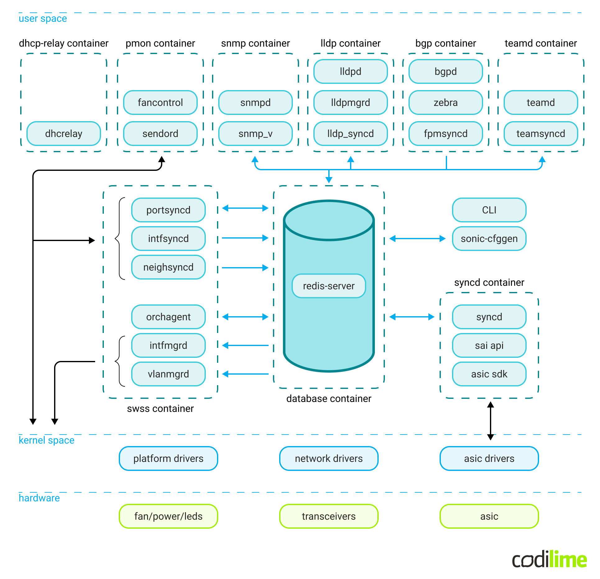
The main components include:
- Network applications, responsible for higher-level management of network functionalities; for example, BGP or SNMP.
- A central Redis container. This is used both as runtime storage and as a means of communication for other parts of the system. It consists of multiple databases, responsible for system configuration, system state, statistics etc. A unique database worth mentioning is the ASIC_DB, which is used for both steering and reflecting the underlying dataplane (ASIC) configuration.
- SwSS container. The Switch State Service (SwSS) is a collection of processes essential for communication among all SONiC modules. It coordinates communication between the network applications, the database and the system kernel. A unique component worth mentioning is the Orchestration Agent, responsible for interpreting the control configuration and setting the dataplane config accordingly.
- SyncD container. This is meant to provide synchronization between the ASIC database (ASIC_DB) representation and the switch’s actual hardware/ASIC using SAI.
This is just a high-level overview of the parts we find important because we needed to actively deal with them in this project. For a detailed description of the architecture, please refer to the official SONiC Wiki ![]() page.
page.
More about Switch Abstraction Interface (SAI)
The Switch Abstraction Interface ![]() is at the heart of the SONiC dataplane configuration. It’s an open-source set of tools for interfacing with general vendor-agnostic switch functionalities. It’s used by SONiC as an isolation layer between the generic SONiC functionalities and the hardware-specific platform details.
is at the heart of the SONiC dataplane configuration. It’s an open-source set of tools for interfacing with general vendor-agnostic switch functionalities. It’s used by SONiC as an isolation layer between the generic SONiC functionalities and the hardware-specific platform details.
Practically speaking from the user’s (developer’s) perspective, SAI is a collection of definitions of various data structures and function signatures used to represent and configure generic switch capabilities, and put in C header files ![]() . There are also auto-generated tools for SAI attribute validation, serialization and more in the meta directory
. There are also auto-generated tools for SAI attribute validation, serialization and more in the meta directory ![]() .
.
It’s the responsibility of the ASIC vendor to provide a specific SAI implementation for their hardware, in order to support a given SAI version:
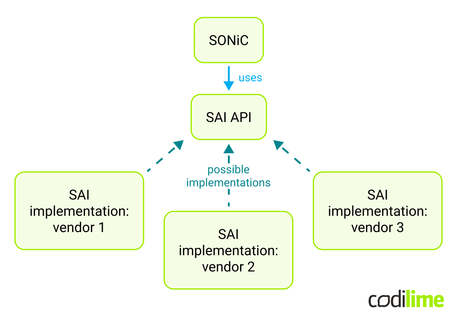
Given that the SAI specification has to be implemented by the hardware chip vendors, adding changes to SAI isn’t really an option in the case of small teams like ours. It’s much easier to experiment with SONiC control plane features using the existing SAI, rather than customizing SAI itself.
SAI is versioned. It is divided into features with mandatory and optional support from the implementation provider (ASIC vendor). It’s worth mentioning that a SAI implementation provider is allowed to add custom SAI features and document that functionality for the user.
Use case description
In our use case it is assumed that GTP-U traffic is distributed by a SONiC switch among a set of endpoints. Packet distribution is based purely on the GTP-U TEID field value and no other action is required (meaning the switch’s “distribution logic” only sets the next hop address). The endpoints’ functionality may take different forms, like physical devices, VMs (as a VNF - Virtual Network Function) or Kubernetes pods (as a CNF - Cloud-Native Network Function) - it does not impact the SONiC implementation.
Our example use case (in its simplest form with only two endpoints) is presented in the picture below:
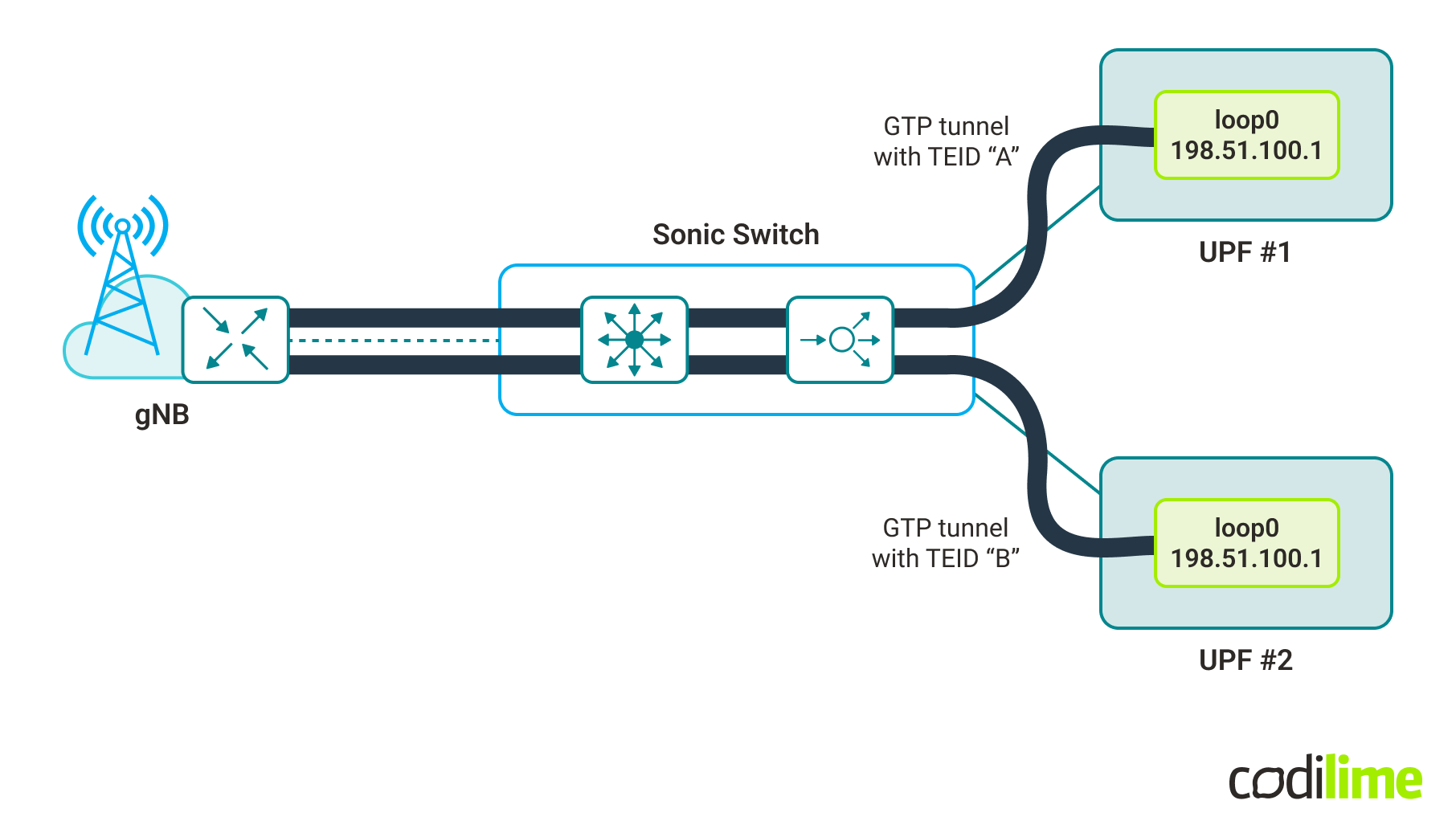
In this simple case, both endpoints have the same IP address for their loopback interface (which is used as the destination IP in packets carrying GTP-U). As such, the switch does not need to change the destination IP, only sets/chooses the appropriate next hop IP (one could say there are multiple paths to the destination and the desired one is chosen based on the TEID field value).
What is worth noting is that such load balancing must be predictable in the sense that it must be possible to predict/calculate (based on the TEID value) to which endpoint a packet will be sent - i.e. the endpoint providing the GTP-U tunnel termination functionally must be configured before receiving the GTP-U packet. This is done by a control plane function that must know the endpoint responsible for the particular TEID.
Before we dig into the solution, let’s focus for a moment on the GTP-U protocol. It is used in mobile networks and according to the 3GPP specification ![]() :
:
“The GTP-U protocol entity provides packet transmission and reception services to user plane entities in the RNC, SGSN, GGSN, eNodeB, SGW, ePDG, PGW, TWAN, MME, gNB, N3IWF, and UPF. The GTP-U protocol entity receives traffic from a number of GTP-U tunnel endpoints and transmits traffic to a number of GTP-U tunnel endpoints. There is a GTP-U protocol entity per IP address.
The TEID in the GTP-U header is used to de-multiplex traffic incoming from remote tunnel endpoints so that it is delivered to the user plane entities in a way that allows multiplexing of different users, different packet protocols and different QoS levels. Therefore no two remote GTP-U endpoints shall send traffic to a GTP-U protocol entity using the same TEID value except for data forwarding as part of mobility procedures.”
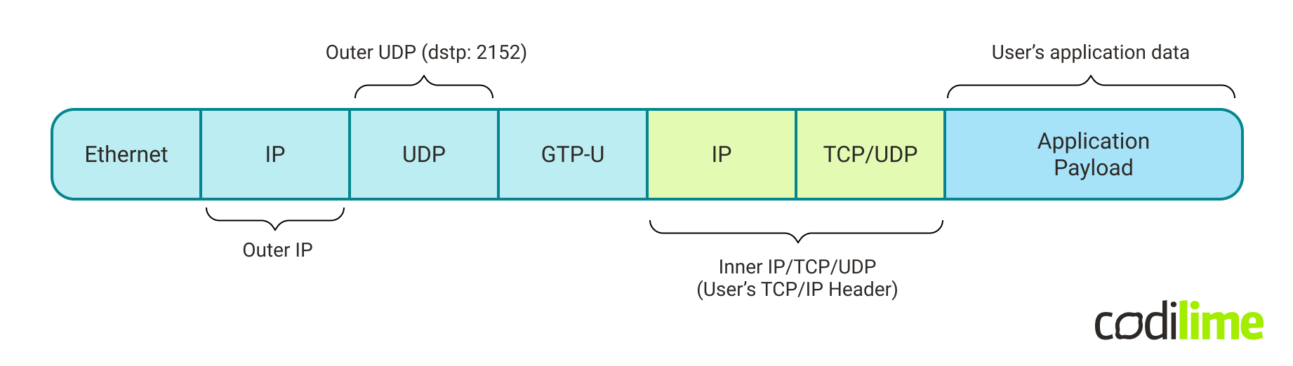
In other words GTP-U is used for carrying user data within the mobile core networks and between the radio access networks and the core networks. GTP-U is a part of the GTP protocol, which additionally contains GTP-C and GTP’. GTP-C is responsible for carrying the signaling messages (between Gateway GPRS Support Nodes and Serving GPRS Support Nodes) while GTP’ handles charging data.
GTP can be carried in UDP or TCP datagrams, version 1 is UDP only and hereafter we assume usage of version 1. IANA assigned port numbers are: 2123 for GTP-C, 2152 for GTP-U and 3386 for GTP’.
The protocol stack for GTP-U packets (carried as UDP payload) is shown in the picture below:
The implementation logic
The intended functionality (for our use case) is to extract TEID field values from GTP-U packets. To be able to do that, first it has to identify the GTP-U packets. Looking at the protocol stack, GTP-U packet identification can be done by filtering for IP packets carrying UDP datagrams with destination port 2152.
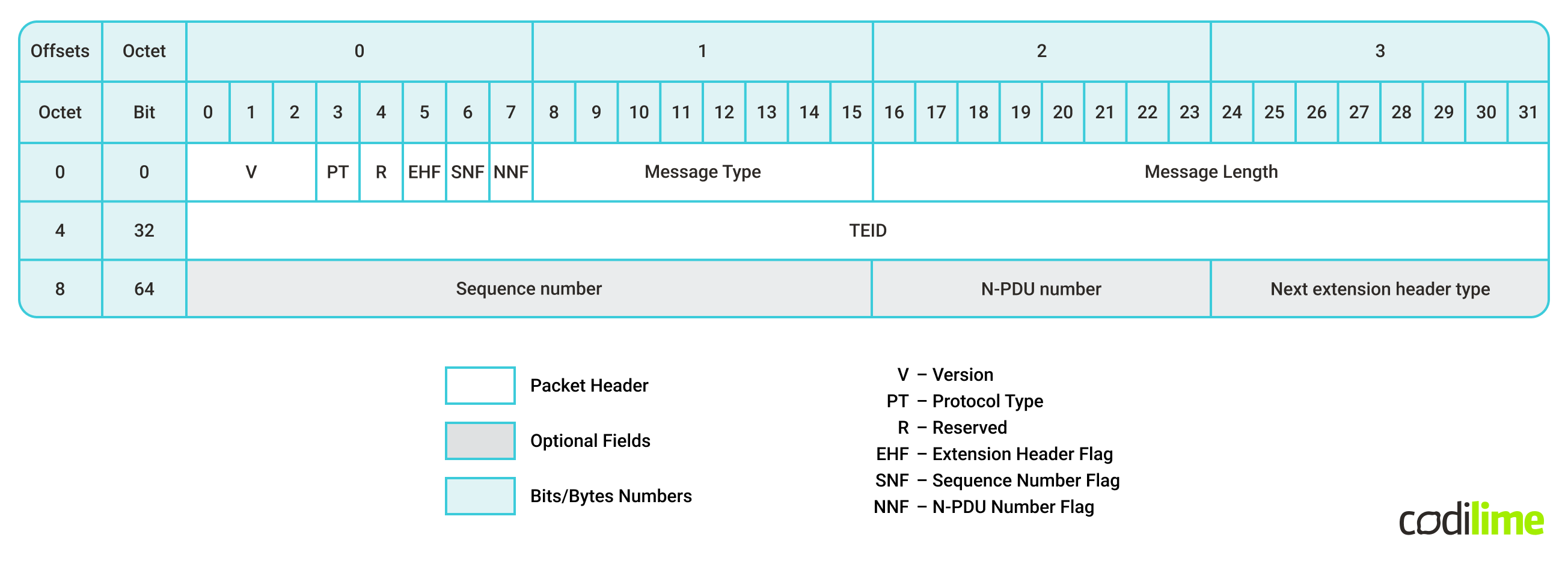
Looking at the GTP v1 packet header, one can see that the TEID value is held between the bits number 32 and 63 of the header (which itself is the payload of the UDP packet). In terms of bytes, the TEID field starts at the 4th byte of the GTP header and is 4 bytes long.
Choosing the right approach for the use case
In general, any functionality which is supposed to be performed by an ASIC chip, must be supported by SAI (included in SAI specification) and implemented by the ASIC vendor of choice (vendors may implement different versions of SAI spec). Because of that, our first task was to look for available features in SAI which could fulfill the needs of our use case. GTP protocol as such is not supported (so it is not possible to get a TEID value in a simple, built-in way; e.g. referencing this field as is done for TCP destination port number). On the other hand, SAI supports the concept of a User-Defined Field (UDF), which allows the extraction of arbitrary field(s) from selected packets. UDF can be used in the context of:
- hash value calculation - e.g. hash for ECMP
 or LAG ,
 - Access Control Lists (ACL) - with the extracted field value as qualifier.
At first glance, the use case seems to fit into the ECMP (Equal-Cost MultiPath) scenario with hash calculation based on TEID (extracted by UDF) since, from SONiC’s perspective (working in L3 mode), there are multiple paths to the destination and it has to forward to one of them. However, there is a second requirement in the use case - predictability in terms of which endpoint is selected. This selection depends on the algorithm used for hash calculation. At the time of writing, the SAI specification allows a choice of hash algorithm for the switch from the following (source: SAI Switch Interface definition ![]() ):
):
/**
 * @brief Attribute data for #SAI_SWITCH_ATTR_ECMP_DEFAULT_HASH_ALGORITHM
 * and #SAI_SWITCH_ATTR_LAG_DEFAULT_HASH_ALGORITHM
 */
typedef enum _sai_hash_algorithm_t
{
    /** CRC based hash algorithm */
    SAI_HASH_ALGORITHM_CRC = 0,

    /** XOR-based hash algorithm */
    SAI_HASH_ALGORITHM_XOR = 1,

    /** Random-based hash algorithm */
    SAI_HASH_ALGORITHM_RANDOM = 2,

    /** Lower 16-bits of CRC32 based hash algorithm */
    SAI_HASH_ALGORITHM_CRC_32LO = 3,

    /** Higher 16-bits of CRC32-based hash algorithm */
    SAI_HASH_ALGORITHM_CRC_32HI = 4,

    /** CRC using CCITT polynomial based hash algorithm */
    SAI_HASH_ALGORITHM_CRC_CCITT = 5,

    /** Combination of CRC and XOR based hash algorithm */
    SAI_HASH_ALGORITHM_CRC_XOR = 6,

} sai_hash_algorithm_t;
Though the algorithms are predefined, they still have parameters which are chosen by the vendor implementing SAI. In consequence, even when the same algorithm is used for the packet, the resulting hash can differ on different platforms. In a particular switch or even in a given ASIC chip this should be consistent (the hash for a given packet is always the same) though it would not be possible to calculate it by hand, unless the implementation details are known (which is unlikely as most ASIC vendors do not publish their SAI implementation, which includes hash functions). Additionally, vendors could change or update the algorithm’s parameters leading to different hash values after the SAI layer is updated on the switch. While for ECMP or LAG this is perfectly acceptable behavior, it could be problematic in the considered use case.
Fortunately, the second option - making use of ACLs (Access Control Lists) with UDF is better suited for setting the target endpoint based on the TEID value. In this approach, UDF is responsible for TEID value extraction and ACL for packet filtering (IP packets carrying GTP-U protocol) and forwarding to specific endpoint. This approach is able to give full control over specifying the target endpoint for a given packet (based on TEID value), thus it fulfills the requirement of the use case.
As a result, we have chosen to utilize the concept of UDF-based ACLs.
The solution’s assumptions and specifications
The GTP TEID field has a length of 32 bits (4 bytes). Depending on the number of endpoints, the actual number of bits taken into account can be reduced. For example, one bit is enough to load-balance between two endpoints, two bits to four endpoints, etc. Generally, one can use the bits of least significance. However this assumes that TEID values are assigned uniformly (meaning it is equally probable for each value to be used, the assignment is not based on chosen ranges, etc.)
Note: a number of endpoints (to which load balancing is done) being a power of 2 (2^n) makes the distribution easier to implement.
The considered use case assumes that there are two endpoints, each connected with a SONiC device using a specific connectivity subnet. For the scenario, the value of the last bit of TEID field (from GTP-U header) is enough to set the next hop for the packet; i.e.:
- if last bit of TEID == 0 -> set next hop IP: IP_ADDRESS_A
- if last bit of TEID == 1 -> set next hop IP: IP_ADDRESS_B
In reality one needs to ensure that only the intended GTP-U packets are matched for redirection (match based on inbound port, IP Protocol type = UDP, UDP destination port = 2152, additionally it might be required to match IP source and/or destination address). Such processing, for a given packet, could look like this (symbol description):
IF inbound_port != Port0 OR ip_protocol != udp OR udp_dst_port != 2152
    action(back_to_standard_processing)
ELSE IF last_bit_of_teid_field == 0
    action(set_next_hop_ip: IP_ADDRESS_A)
ELSE IF last_bit_of_teid_field == 1
    action(set_next_hop_ip: IP_ADDRESS_B)
Note: the switch port number and IP addresses are examples (values depend on the setup configuration). The IP Protocol, UDP destination port and TEID last bit values are use case-specific.
ACL handling by SAI and SONiC
The SAI ACL Table defines the stages ![]() at which ACL rules are performed in the SAI pipeline:
at which ACL rules are performed in the SAI pipeline:
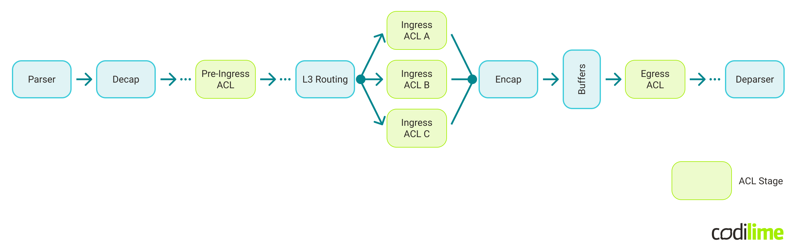
For each stage there is a defined set of actions which can be performed. In the context of the load balancing use case, one can use:
- Pre-Ingress ACL stage with an action “set VRF” (packet is set to a particular VRF based on ACL match rules).
- Ingress ACL stage with an action “REDIRECT” (packet is redirected to an interface, a next hop, or a next hop group, based on ACL match rules).
As the SONiC project currently only supports the Ingress and Egress ACL stages - the Ingress stage has been selected for this use case.
The implementation
So, we had decided on the logic, then the time came to approach the implementation.
What were our options?
In general, there are two ways: to find and configure or adapt a suitable existing solution, or to develop it from scratch. It is reasonable to use available features (whenever possible) and if necessary to add only the missing parts. Initial research led us to two possible solutions: P4 Runtime (part of PINS ![]() ) or adding support for UDF-based ACLto the SONiC code.
) or adding support for UDF-based ACLto the SONiC code.
First approach - SONiC PINS and P4 Runtime
PINS (P4 Integrated Network Stack) is a relatively new initiative, which aims at bringing SDN capabilities and P4 programmability to traditional routing devices. It uses P4 Runtime (P4RT) as a new control plane interface. The P4 Runtime API ![]() is a control plane specification for controlling the data plane elements (in our case in SONiC switch) defined or described by a P4 program.
is a control plane specification for controlling the data plane elements (in our case in SONiC switch) defined or described by a P4 program.
PINS was first introduced as part of the SONiC release 202111. Among other aspects, it added the P4 Runtime application to SONiC. The role of this application is to listen to a remote SDN controller (which communicates over the P4RT protocol) and create entries in SONiC databases.
After checking the documentation and usage examples, it seemed that UDF-based ACLs should be supported (at least to some extent), which would essentially fill the SONiC gap in the context of our use case. So, we decided to give it a try.
What we can say today is that employing P4RT for a use case like ours proved to be neither fast nor effortless. The entry threshold turned out to be relatively high as we encountered some challenges. For example, the default options for the SONiC build do not include PINS and in consequence the SONiC upstream builds do not contain PINS components either. It required a little effort to build our own virtual switch with PINS support. Another issue was the lack of working examples, as the ones found in the SONiC PINS repository required some modifications to work.
From our perspective, the official PINS tutorial ![]() was oriented around PINS usage in a physical switch. Given that, there was no working p4info file for us to use with the software switch in the first place. Generally speaking, a software switch would be a better fit (more robust, replicable) for an entry-level tutorial, which would allow beginners to “learn by doing” and then adapt this knowledge to their use case. So, we wish there was an “out-of-the-box” working configuration of a virtual switch available, as this would have greatly supported our work from day one.
was oriented around PINS usage in a physical switch. Given that, there was no working p4info file for us to use with the software switch in the first place. Generally speaking, a software switch would be a better fit (more robust, replicable) for an entry-level tutorial, which would allow beginners to “learn by doing” and then adapt this knowledge to their use case. So, we wish there was an “out-of-the-box” working configuration of a virtual switch available, as this would have greatly supported our work from day one.
Given the limited time frame we had for the project and the challenges we faced, we decided not to use PINS in our solution.
Second approach - developing a tailored solution
Consequently, the development of the required features was the only option left (meaning we had to implement support for UDF and UDF-based ACLs). In a nutshell, in order to instruct a SONiC switch to perform the desired logic, we need to feed it with the desired configuration through CONFIG_DB (Redis database), from where it is pulled by the Orchestration Agent (Orchagent), processed and pushed to ASIC_DB (another Redis database). Finally, it is handed over to the switch’s ASIC by SyncD and SAI API.
To achieve that, we modified Orchestration Agent (i.e. we added support to create UDF objects, then ACL tables and ACL rules were modified to support UDF as a qualifier). Another modified element was saimetadata library (it enriches the SAI API with runtime metadata). As a result, additional changes were required in components dependent on saimetadata: Orchagent and SyncD.
From the very beginning, our focus was on the use case in order to keep things simple and efficiently utilize the time allotted for the project. As a result, our implementation is not intended for generic usage (e.g. UDF implementation is intended to be used with ACLs only and as such does not support hashes).
For more information about the development process and implementation details, we invite you to read the second part of our SONiC development article series - link.


