


Linux has a rich networking background; from routing and bridging up to complicated EVPN deployment. It’s also extremely popular in the networking world - almost every home router is based on that OS. However, such deployments concentrate mostly on a simple scenario: basic routing with one static default route along with simple FW and NAT. By now you probably already know that Linux can do much more. There are even distributions built on top of kernel networking functions such as VyOS, OpenWRT, and IPFire.
In this blog, we want to take a look at Linux from a different angle, namely from an ISP network engineer point of view. As it is quite common to have network functions or features explained to a developer or SysOps based on analogies related to a Linux system, we think that the opposite approach is missing. Therefore in the article we want to have it the other way around: we aim to show network engineers already highly experienced in ISP, DC or enterprise networks how to achieve functionalities commonly used using a linux system. To be clear, we are not saying that a solution built in a Linux-based device can be a substitute for a hardware device in each and every situation. No, such an approach is applicable in some situations and it requires both knowledge and experience to understand which.
We also will not concentrate on a performance point of view but from more of a feature perspective. In the following sections, we will compare common features that can be found in the Telco networks and we will show how to deploy them on Juniper devices as well as using Linux.
This article is for network engineers who already have some experience in building network solutions and services. The acronyms used throughout the text are commonly used in the ISP/Telco world and should be understood by most readers. Some experience in Linux networking is also helpful. To start, we encourage the reader to take a brief look at our Linux network troubleshooting - commands and examples blog post where we present the most common Linux networking commands. For more advanced Linux networking features, the How to drop a packet in Linux in more ways than one blog post is available. And lastly, if a reader is interested in what can be achieved with a combination of open source network solutions, one can refer to the three-part webinar series starting with this video: The modern, interoperable DC - Part 1: Solving "last mile" problems with BGP.
Environment
Before we jump to specific features, we should first discuss the environment that is going to be used:
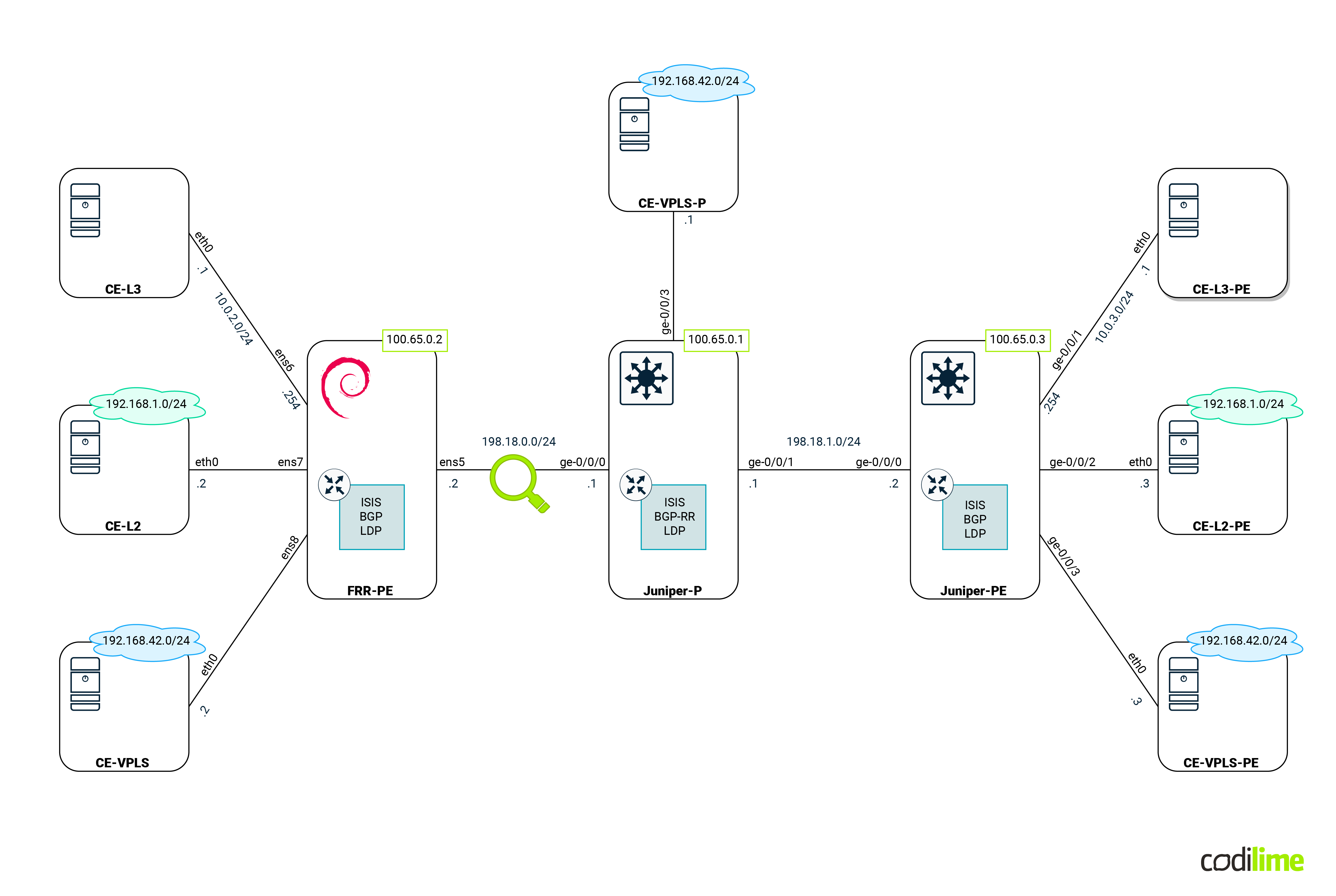
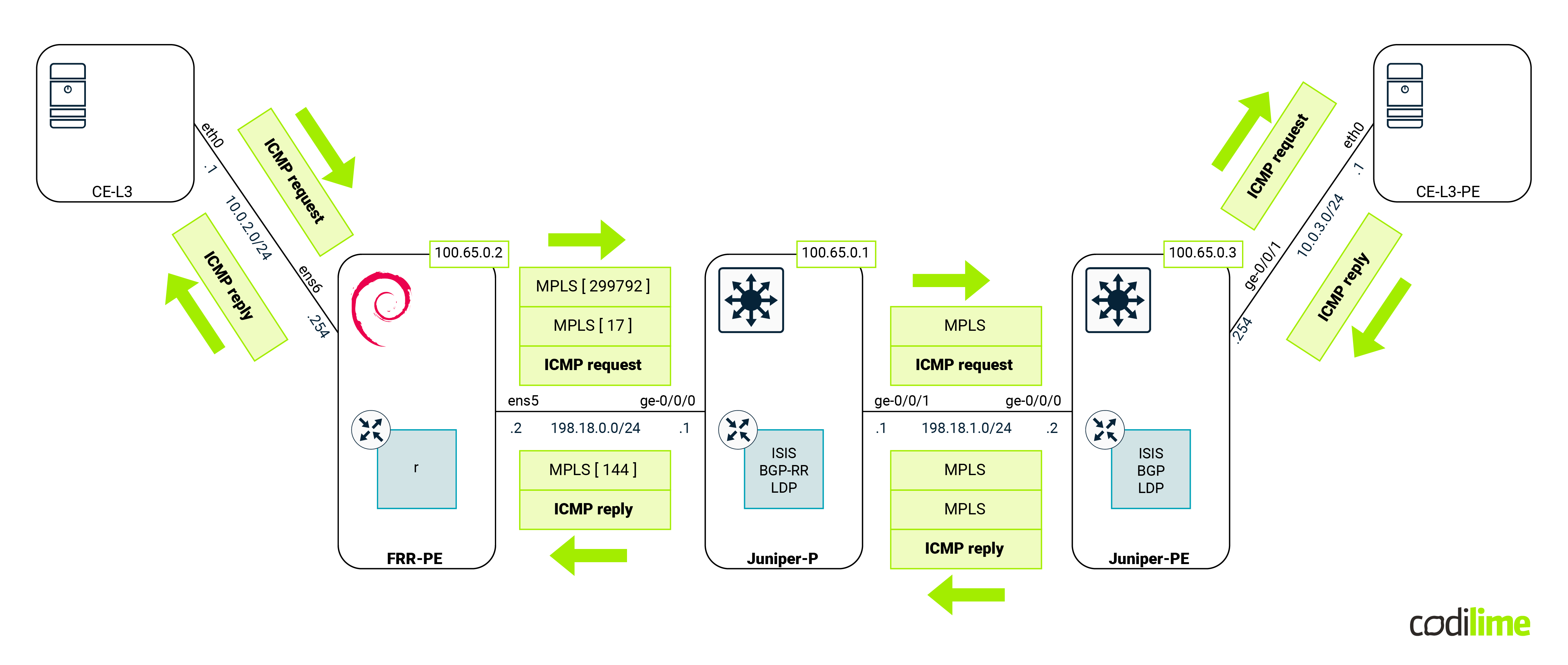
Devices that can be seen in the diagram above are:
- PE routers (Juniper and our Linux box) - those devices will have all features that are going to be compared in this blog deployed. For Linux we used Debian, but any distro with a recent kernel and OVS will do.
- P router (Juniper) - the main task for this device is to forward MPLS traffic between PE. Its existence will also enforce PE behavior that we will cover in the following sections (such as a double MPLS push). For the last scenario (covering VPLS) that device will act as a P/PE device.
- CE devices (Linux Alpine) - these VMs will act as customer equipment and will communicate with each other, creating traffic to cross PE routers.
- Magnifying glass - shows where the traffic will be captured later on.
The whole environment will be emulated in GNS3 software. GNS3 ![]() is used by hundreds of thousands of network engineers to emulate, test and do multiple marvelous things related to networks. It allows you to create and run a small/medium topology on just your laptop or home PC. Each device in GNS3 can be either VM-based or container-based. In this post, we will use:
is used by hundreds of thousands of network engineers to emulate, test and do multiple marvelous things related to networks. It allows you to create and run a small/medium topology on just your laptop or home PC. Each device in GNS3 can be either VM-based or container-based. In this post, we will use:
-
For the FRR-PE device, a Debian 12.1 generic cloud image with the following components:
- Linux kernel for data plane: version 6.1.52-1

- FRR for control plane protocols such as BGP/ISIS: version 9.0.1
- OVS for L2 policing: version 3.0.1
- Linux kernel for data plane: version 6.1.52-1
For those who have worked with Cisco devices, it is worth mentioning that configuration of FRR resembles the configuration of Cisco routers, so it should be easy to understand.
- For Juniper devices, a Juniper vEX. We decided to use Juniper as it is quite popular in the Telco environment and vEX (version 23.2R1) was recently released for free here . As Juniper vEX comes with a complete device chipset emulation (as opposed to other vendors such as Arista and Nvidia that add control plane software on top of the Linux kernel) its behavior should be very similar to a physical box.
- For all CE devices, Alpine Linux 3.16 with kernel 5.15.71-0
Without any further ado, let us dive into the features that can be found in ISPs.
ISP features
Most telco environments are built on top of the following pieces:
-
Data plane features:
- PBR L2/L3
- VRF
- MPLSz
-
Control plane features:
- ISIS
- BGP
- LDP
-
Services:
- MPLS (LER, LSR)
- L3VPN
- EVPN
- L2circuit
- VPLS
While the above list is not by any means a complete one, it covers most of the basics. In the following sections, we will attempt to cover the configuration of all of the above features on both Linux and Juniper devices for easier comparison.
Data plane features
L2/L3 PBR
If you’re not familiar with layer 3 PBR, read our article What is policy based routing. As L3 PBR has already been described there, we will focus on the Layer 2 PBR that is available on Linux when using OVS.
According to the author description, OVS is a, “production quality, multilayer virtual switch [...] supporting standard management interfaces and protocols (e.g. NetFlow, sFlow, IPFIX, RSPAN, CLI, LACP, 802.1ag).” However this description does not do justice to this product. It can do much more when configured using OpenFlow rules. OVS comes in three flavors:
- Kernel (as in kernel module) - this is the version we will use as it is the most portable version and easiest to use.
- DPDK - this version offers the same functionality as the kernel one but with much higher performance, at the cost of more complex deployment.
- SmartNIC offloaded - several SmartNICs accelerate OVS by offloading its functionality to the hardware - they offer the highest performance (notable mentions are NICs from Nvidia, Netronome, and Intel). One can refer to the Hardware offloading in software-defined networking blog post for more information.
OVS will be required to implement some of the features that will appear later in this blog, but for now we will create a simple bridge with two rules in it on our Debian VM:
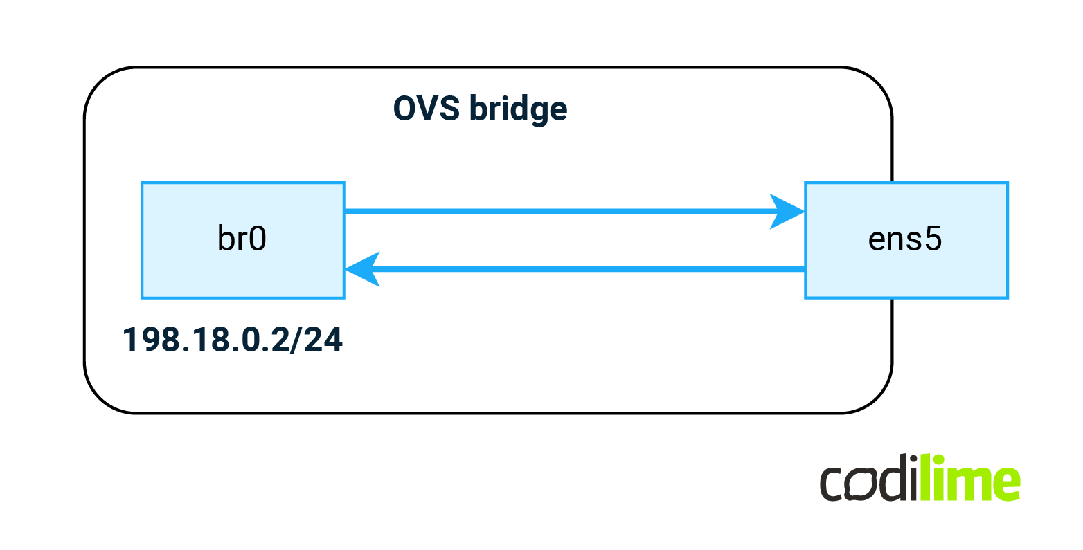
All traffic received on ens5 will be forwarded to the br0 interface (IRB or SVI type of interface) and all traffic from the br0 interface will be sent via the ens5 interface (the ens5 interface is already present in the system):
root@FRR-PE:~# ovs-vsctl add-br br0
root@FRR-PE:~# ovs-vsctl add-port br0 ens5
root@FRR-PE:~# ovs-ofctl del-flows br0
root@FRR-PE:~# ovs-ofctl add-flow -O OpenFlow13 br0 "priority=90,in_port=ens5 actions=output:br0"
root@FRR-PE:~# ovs-ofctl add-flow -O OpenFlow13 br0 "priority=90,in_port=br0 actions=output:ens5"
Two important notes here:
- By default, OVS acts as a normal switch, handling VLANS MACs, etc. We want full control over OVS and so we remove all existing config with the del-flows knob.
- All rules in OVS are parsed according to their priority value (higher values are served first). Since we will be adding some entries later on, we want to leave some space below and above.
Although at this point there is no reason to use OVS instead of just using the ens5 interface directly, having this configuration in advance will save us time later on.
VRF
Virtual routing and forwarding (VRF) is a solution that allows multiple, separate instances of a routing table to co-exist within the same device at the same time. One or more interfaces (logical or physical) may be attached to VRF. AS a result, packets are only forwarded between interfaces inside the same VRF. VRFs are the IP (Layer 3) equivalent to a VLAN. In Linux, VRF has been supported in the kernel since version 4.8 and they can be configured using the following CLI commands:
root@FRR-PE:~# ip link add blog_l3 type vrf table 10
root@FRR-PE:~# ip l set up blog_l3 #ip l is and abbreviation for ip link command
root@FRR-PE:~# ip l set ens6 master blog_l3
We used the blog_l3 name here. The VRF name can have any value as long as it is kept in sync with FRR configuration. It’s just being used to identify the VRF. Each VRF must be associated with the routing table (where routes will be kept), as a routing table is an integral part of the VRF. While you can have routing tables without VRFs and do advanced PBR on them, you can’t have VRF without a routing table assigned.
One should not mix VRF with the network namespace that can be encountered in Linux when using containers. A single network namespace can contain several VRFs. Also each namespace has a dedicated set of FW rules, while VRFs share them (within the namespace). The rough equivalent to network namespace in Linux would be the logical system in Juniper devices.
MPLS
Multiprotocol Label Switching (MPLS) is a routing technique in telecommunication networks that allows moving data from one node to the next based on external labels rather than destination network addresses. This allows the device to shrink down the decision tree as multiple IPv4 prefixes (the whole IPv4 packet is encapsulated in MPLS) can share the same label. In the Linux kernel, MPLS has been supported since kernel version 4.5. However, one must remember that support is limited to L3 encapsulation only. The whole Ethernet frame cannot be encapsulated easily in Linux.
To enable MPLS support first one must load the appropriate kernel modules:
root@FRR-PE:\\~# modprobe mpls_router
root@FRR-PE:\\~# modprobe mpls_iptunnel
Next there are two sysctl knobs in Linux that one must be aware of.
root@FRR-PE:~# sysctl -w net.mpls.conf.br0.input=1
This one enables MPLS packet processing on the br0 interface (the one we have created earlier). This should be enabled on all L3 interfaces that participate in MPLS routing.
root@FRR-PE:~# sysctl -w net.mpls.platform_labels=1048575
This one specifies the max label value that will be accepted by the Linux kernel. Since Juniper uses labels from a whole range, we need to accept those values as well (please note that one can find documents on the Internet that suggest using value 65535 here - however this will not work with Juniper or other network devices).
Control plane features
ISIS
ISIS is one of two routing protocols that are common in the ISP environment. It is mostly used to advertise loopback IPs of participating devices. Those addresses will be later used to establish iBGP sessions (in data center networks, ISIS is often replaced by the eBGP protocol in order to achieve IGP-free architecture). Below we can find the configuration extract for the Juniper P device (PE config will be similar) as well for FRRouting running on Debian VM:
Juniper config
root@Juniper-P> show configuration interfaces ge-0/0/0
unit 0 {
   family inet {
       address 198.18.0.1/30;
   }
   family iso;
   family mpls;
}

root@Juniper-P> show configuration interfaces lo0
unit 0 {
   family inet {
       address 100.65.0.1/32;
   }
   family iso {
       address 49.0100.056.0000.0001.00;
   }
}

root@Juniper-P> show configuration protocols isis
interface ge-0/0/0.0;
interface ge-0/0/1.0;
interface lo0.0 {
   passive;
}
level 2 wide-metrics-only;
level 1 disable;
FRR config
FRR-PE# show running-config
[...]
interface br0
description Juniper P
ip address 198.18.0.2/30
ip router isis blog
isis circuit-type level-2-only
mpls enable
exit
!
interface lo
ip address 100.65.0.2/32
ip address 169.254.0.2/32
ip router isis blog
isis circuit-type level-2-only
isis passive
exit
!
router isis blog
is-type level-2-only
net 49.0100.065.0000.0002.00
exit
[...]
BGP
BGP is the second routing protocol that is common in the ISP environment. It is mostly used to advertise a set of IPv4/IPv6 prefixes as well as services (L3VPN, EVPN etc) that are available on participating devices. Unfortunately in FRR the L2VPN (VPLS and l2circuit) are not supported so we will advertise only L3VPN here. BGP can be used to advertise EVPN that is more common in data center networks (sometimes it can be found in Telco as it’s superior to VPLS in many ways). For more information about EVPN see our blog post dedicated to this topic, it can be found here: xxxx Below we can find the configuration extract for Juniper P device (PE config will be similar) as well for FRRouting running on Debian VM:
Juniper config
Please note that Juniper P is acting as BGP RR.
root@Juniper-P> show configuration routing-options
router-id 100.65.0.1;
autonomous-system 64512;

root@Juniper-P> show configuration protocols bgp
group blog {
   type internal;
   local-address 100.65.0.1;
   family inet-vpn {
       unicast;
   }
   cluster 100.65.0.1;
   neighbor 100.65.0.2;
   neighbor 100.65.0.3;
}
FRR config
FRR-PE# show running-config bgpd
[...]
router bgp 64512
neighbor blog peer-group
neighbor blog remote-as internal
neighbor blog update-source 100.65.0.2
neighbor 100.65.0.1 peer-group blog
!
address-family ipv4 unicast
 no neighbor blog activate
exit-address-family
!
address-family ipv4 vpn
 neighbor blog activate
exit-address-family
LDP
LDP is a control plane protocol that generates and exchanges labels between routers. As a reminder of the concepts of management, control and data planes in the network devices we encourage the reader to check out the article Management vs. Control vs. Data Planes in a Network Device which explains these topics. Each router will locally create labels for its prefixes and will then advertise those label values to its neighbors. Such MPLS labels will be later used to encapsulate the traffic (however the behavior as to what is going to be encapsulated is different between Juniper and Linux). LDP can also be used (and this is supported by FRR) to advertise L2circuit and VPLS services. Configuration of such services will be covered in later sections. Below we can find the configuration extract for the Juniper P device (PE config will be similar) as well as for FRRouting running on Debian VM:
Juniper config
root@Juniper-P> show configuration protocols ldp
interface ge-0/0/0.0;
interface ge-0/0/1.0;
interface lo0.0;
FRR config
FRR-PE# show running-config ldpd
[...]
mpls ldp
router-id 100.65.0.2
!
address-family ipv4
 discovery transport-address 100.65.0.2
 !
 interface br0
 exit
 !
 interface lo
 exit
 !
exit-address-family
!
exit
ISP services
MPLS POP/PUSH/SWAP
As mentioned before MPLS is used to switch passing traffic (LSR aka P router) as well as to encapsulate traffic at the edge (LER aka PE router). In order to act as an edge router, the device must support MPLS POP/PUSH operations. In some cases LER devices must support double MPLS push action (to encapsulate transport and service labels). Double MPLS will be covered in the L3VPN section. Here we will show that Linux is capable of POP/PUSH operation when acting as a PE device. The following sections will cover Juniper PE as well as Linux FRR configuration. Later we will display service status on both devices. At the end we will perform verification by sending custom traffic and capturing that traffic between Linux and P router. That capture should show properly encapsulated traffic.
Juniper
Juniper-PE config
As Juniper will only push MPLS labels for routes where the next hop is reachable via LDP we added static route pointing to the next-hop IP which is assigned on the FRR-PE loopback (see FRR config in the next section for more details):
root@Juniper-PE> show configuration routing-options static
route 100.65.0.12/32 {
   next-hop 100.65.0.2;
   resolve;
}
Juniper-PE status
From this moment, this IP address was reachable via MPLS:
root@Juniper-PE> show route 100.65.0.12


inet.0: 11 destinations, 12 routes (11 active, 0 holddown, 0 hidden)
Limit/Threshold: 1048576/1048576 destinations
+= Active Route, - = Last Active,  \* = Both


100.65.0.12/32     \*\[Static/5] 00:39:07, metric2 1
                    >  to 198.18.1.1 via ge-0/0/0.0, Push 300096
                    \[IS-IS/18] 00:32:51, metric 30
                    >  to 198.18.1.1 via ge-0/0/0.0
Linux
FRR-PE config
For the purpose of this subsection we have added explicit-null configuration in the LDP configuration to show MPLS POP support on Linux. Please note the LDP adjacency in FRR had to be severed in order to advertise the new set of labels:
FRR-PE# clear mpls ldp neighbor
We also added a secondary IP on loopback that was used in the static route on Juniper PE. The new configuration for loopback and LDP protocol is shown below:
FRR-PE# show running-config
[...]
interface lo
ip address 100.65.0.12/32
ip address 100.65.0.2/32
ip router isis blog
isis circuit-type level-2-only
isis passive
mpls enable
exit
[...]
mpls ldp
router-id 169.254.0.2
!
address-family ipv4
 discovery transport-address 100.65.0.2
 label local advertise explicit-null
 !
 interface br0
 exit
 !
 interface lo
 exit
 !
exit-address-family
!
exit
FRR-PE status
On Linux the encapsulation behavior is similar to Cisco devices. Everything (if possible) is encapsulated into MPLS as visible for outgoing routes below. For incoming traffic one must display a route from the MPLS protocol (hence -f mpls option) to show the behavior.
root@FRR-PE:~# ip route
[...]
100.65.0.1 nhid 498 via 198.18.0.1 dev br0 proto isis metric 20
100.65.0.3 nhid 499  encap mpls  300080 via 198.18.0.1 dev br0 proto isis metric 20
198.18.0.0/30 dev br0 proto kernel scope link src 198.18.0.2
198.18.1.0/30 nhid 497 via 198.18.0.1 dev br0 proto isis metric 20

root@FRR-PE:~# ip -f mpls route
19 via inet 198.18.0.1 dev br0 proto ldp
20 as to 299792 via inet 198.18.0.1 dev br0 proto ldp
We can see here that outgoing traffic will be encapsulated with MPLS label 300080 while we expect incoming traffic with label 0 (due to the explicit-null configuration) Please note that label 0 is not shown on the output above (for incoming traffic) as local handling of label 0 is defined by standard (and enabled by default). Labels 19 and 20 were assigned by FRR and advertised via LDP to the Juniper-P peer.
Verification
To perform the verification, a ping was executed from Juniper PE router to check POP/PUSH actions on Linux:
root@Juniper-PE> ping 100.65.0.12 source 100.65.0.3 count 4
PING 100.65.0.12 (100.65.0.12): 56 data bytes
64 bytes from 100.65.0.12: icmp_seq=0 ttl=63 time=2.385 ms
64 bytes from 100.65.0.12: icmp_seq=1 ttl=63 time=3.666 ms
64 bytes from 100.65.0.12: icmp_seq=2 ttl=63 time=2.794 ms
64 bytes from 100.65.0.12: icmp_seq=3 ttl=63 time=2.970 ms


--- 100.65.0.12 ping statistics ---
4 packets transmitted, 4 packets received, 0% packet loss
round-trip min/avg/max/stddev = 2.385/2.954/3.666/0.463 ms
At this point we expect MPLS traffic with the following labels as shown in the diagram below:
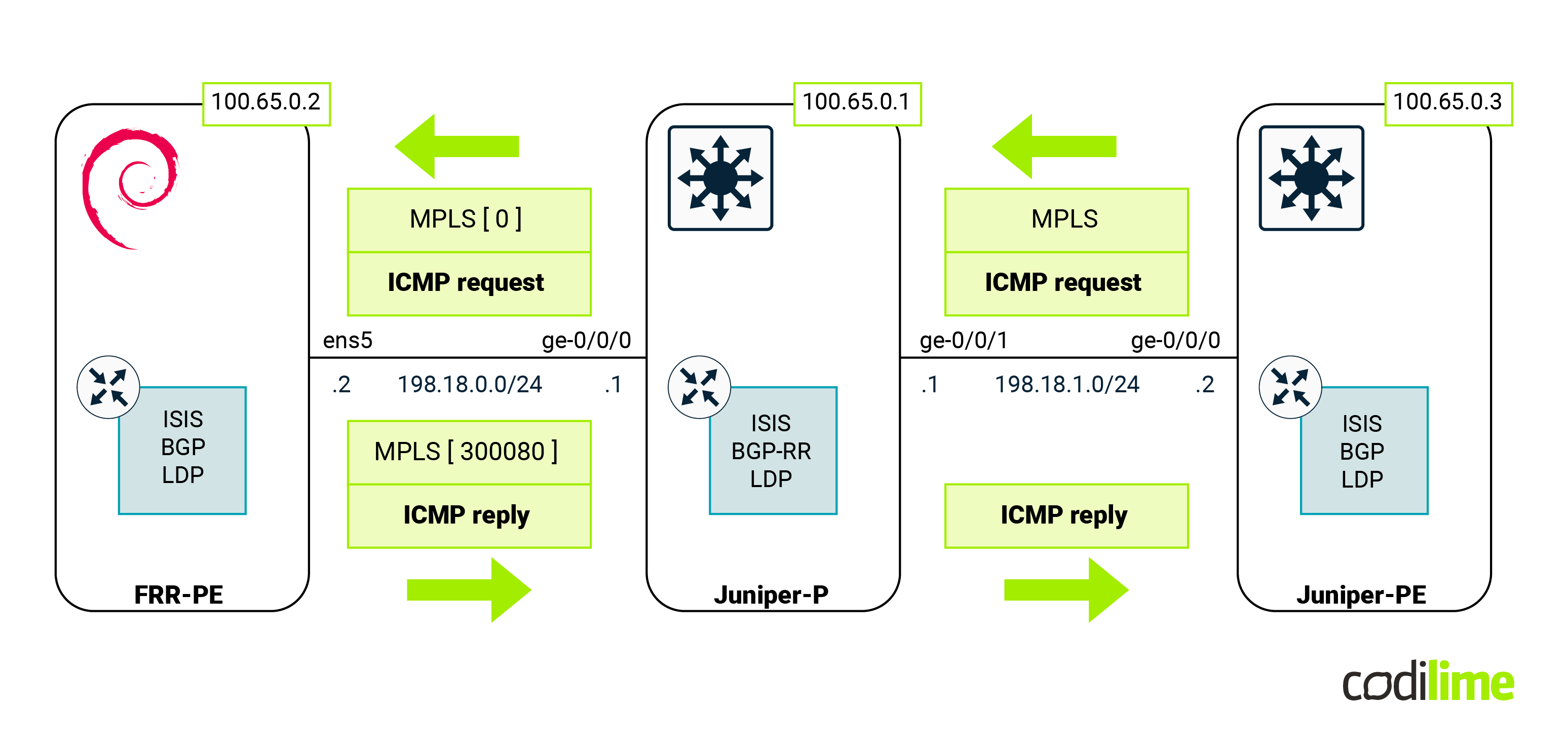
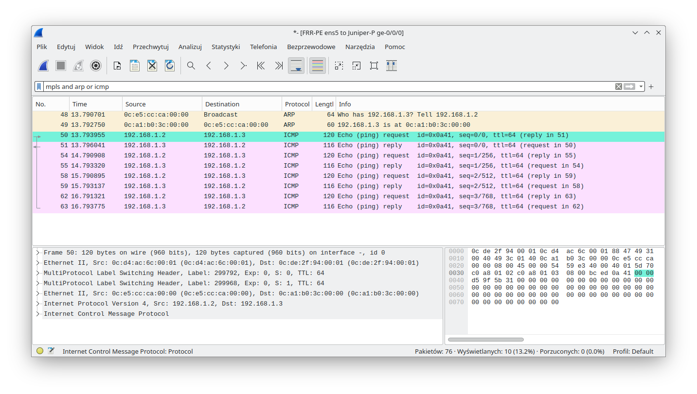
To check this, we launched a packet sniffer (Wireshark) on the link between FRR-PE and Juniper-P devices (this is possible thanks to GNS3). As one can see, MPLS packets were handled by Linux (that performed MPLS POP for the received traffic):
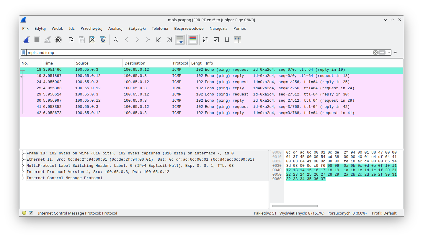
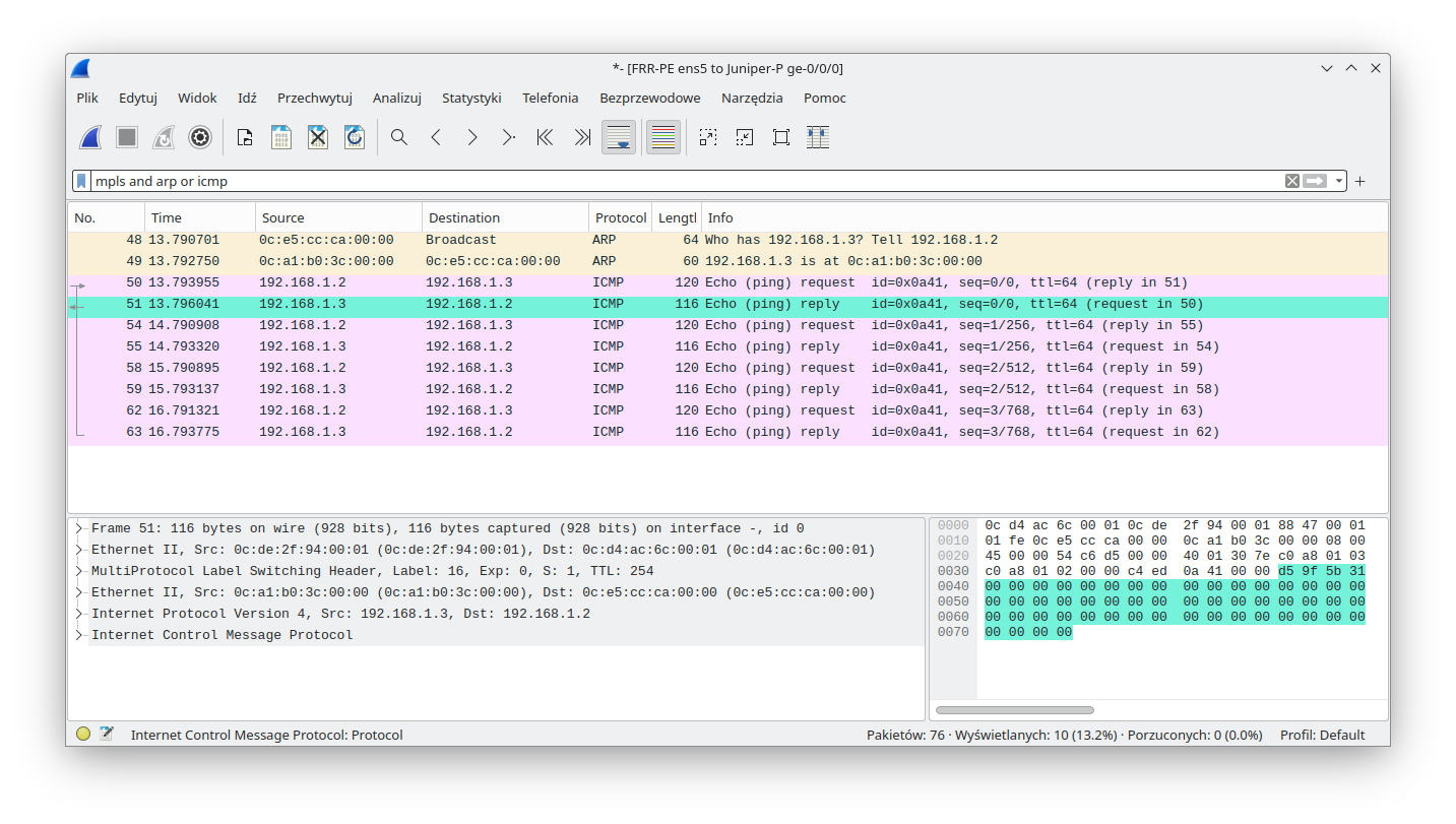
MPLS packets were also sent by Linux (that performed MPLS PUSH):
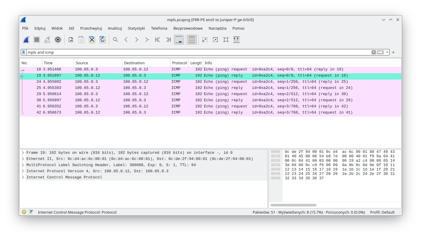
It is important to underline that the symmetry (POP & PUSH) in the label handling shown above is not a normal state regardless of whether a Linux device is used or not. As mentioned, it was forced here on purpose to show the POP and PUSH capabilities of a Linux device, with the help of an explicit-null label.
For the next demo, the configuration was restored to the previous state (explicit null, extra IP on loopback and static route were removed). Double MPLS PUSH on Linux will be presented in the next section. MPLS SWAP, although supported by Linux, was impossible to show on this topology.
L3VPN
The L3VPN service allows ISPs to connect customers' networks together even when IP address space will overlap between customers. This service is based on MPLS as well. In the case of L3VPN, the PE devices must be aware of two labels. The service label (identifying the service on the target PE router) advertised by BGP as well as the transport label (external label in MPLS stack for P router) advertised by LDP. To apply both labels at the same time, Linux will have to perform the double PUSH operation mentioned earlier. Upon receiving the packet on the PE device, there will only be a single label (as explicit-null configuration was removed). After performing the MPLS POP action, the decapsulated IPv4 packet will be placed in the associated VRF. The following sections will cover Juniper PE, Linux FRR, as well as Linux data plane configuration. Later we will display the service status on both devices. At the end, we will perform verification by sending custom traffic and capturing that traffic on the connection between Linux and the P router. That capture should show us properly encapsulated traffic.
Note: In this blog post we are assuming that the reader is accustomed to L3VPN we will not explain route-distinguisher, route target, etc. terminology.
Juniper
On the Juniper PE device we will create a new VRF and assign the ge-0/0/1.0 interface to it. With the following configuration below, connected routes will be advertised by Juniper-PE:
Juniper PE config
root@Juniper-PE> show configuration interfaces ge-0/0/1
unit 0 {
   family inet {
       address 10.0.3.254/24;
   }
}
root@Juniper-PE> show configuration routing-instances blog_l3
instance-type vrf;
interface ge-0/0/1.0;
route-distinguisher 100.65.0.3:10;
vrf-target target:64512:10;
vrf-table-label;
Juniper PE status
We can see here that FRR advertises its connected network in its VRF (network between PE and CE) and from the Juniper-PE point of view, traffic towards the FRR-PE device should be encapsulated in 144/300016 (service/transport) labels.
root@Juniper-PE> show route table blog_l3.inet.0blog_l3.inet.0: 3 destinations, 3 routes (3 active, 0 holddown, 0 hidden) += Active Route, -= Last Active, *= Both
10.0.2.0/24 * [BGP/170] 00:07:43, MED 0, localpref 100, from 100.65.0.1 AS path: ?, validation-state: unverified > to 198.18.1.1 via ge-0/0/0.0, Push 144, Push 300016(top) 10.0.3.0/24 * [Direct/0] 02:23:20 > via ge-0/0/1.0 10.0.3.254/32 * [Local/0] 02:23:20 Local via ge-0/0/1.0
FRR
FRR-PE config
VRF creation and ens6 interface assignment was done in the VRF section. Here we will add FRR config for L3VPN service. We will explicitly add connected routes redistribution:
FRR-PE# show running-config
[...]
interface ens6
ip address 10.0.2.254/24
exit
[...]
router bgp 64512 vrf blog_l3
!
address-family ipv4 unicast
 redistribute connected
 label vpn export auto
 rd vpn export 100.65.0.2:10
 rt vpn both 64512:10
 export vpn
 import vpn
exit-address-family
exit
FRR-PE status
On FRR we can see that L3VPN traffic towards the Juniper-PE device should be encapsulated in 17/299792 (service/transport) labels as this prefix is advertised by Juniper-PE by default with the above configuration applied.
FRR-PE# show ip route vrf blog_l3
Codes: K - kernel route, C - connected, S - static, R - RIP,
      O - OSPF, I - IS-IS, B - BGP, E - EIGRP, N - NHRP,
      T - Table, v - VNC, V - VNC-Direct, A - Babel, F - PBR,
      f - OpenFabric,
      > - selected route, * - FIB route, q - queued, r - rejected, b - backup
      t - trapped, o - offload failure


VRF blog_l3:
C>* 10.0.2.0/24 is directly connected, ens6, 00:10:00
B>  10.0.3.0/24 [200/0] via 100.65.0.3 (vrf default) (recursive), label 17, weight 1, 00:09:23
*                      via 198.18.0.1, br0 (vrf default), label 299792/17, weight 1, 00:09:23
Linux
The configuration from the section describing VRF functionality in Linux will be used in this example.
Verification
An ICMP ping was sent between 2 L3-CE devices attached to FRR-PE and Juniper-PE:
ce-l3:~# ping -c 4 10.0.3.1
PING 10.0.3.1 (10.0.3.1): 56 data bytes
64 bytes from 10.0.3.1: seq=0 ttl=61 time=4.097 ms
64 bytes from 10.0.3.1: seq=1 ttl=61 time=3.328 ms
64 bytes from 10.0.3.1: seq=2 ttl=61 time=3.612 ms
64 bytes from 10.0.3.1: seq=3 ttl=61 time=2.974 ms


--- 10.0.3.1 ping statistics ---
4 packets transmitted, 4 packets received, 0% packet loss
round-trip min/avg/max = 2.974/3.502/4.097 ms
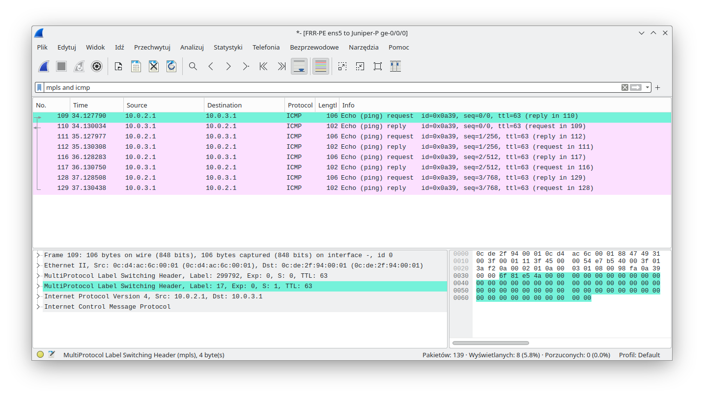
Since the ping was successful, let's concentrate on the MPLS labels that we expect to be found in transit. As usual we will capture traffic between the FRR-PE and Juniper-P devices. The following diagram shows the expected labels:
As we can see from the capture, traffic from FRR-PE is encapsulated twice (double PUSH):
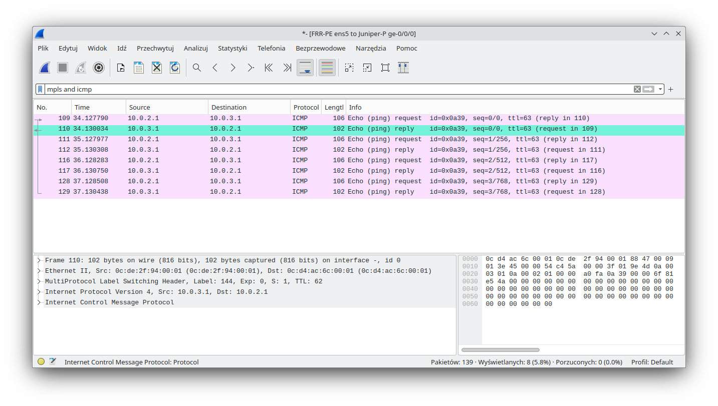
Return traffic towards FRR-PE has single MPLS encapsulation, with the expected MPLS label.
EVPN
Ethernet VPN (EVPN) is one of the latest additions in the block of ISP VPN protocols. It is dubbed as a next-generation, all-in-one VPN technology that provides a wide range of services such as VPLS, VPWS/l2circuit, L3VPN, MC-LAG, etc.
Simplification comes to mind when you think about EVPN - it is largely considered as a unified control plane solution that can use many encapsulations, such MPLS, VxLAN, NvGRE. There are several guides that show how to stitch VPLS with EVPN or MPLS-based EVPN with VxLAN-based EVPN. However those guides are outside the scope of this blog post. Please keep in mind that Linux only supports VxLAN for encapsulation and while the kernel can support the VPWS/l2circuit services advertised by EVPN (as Juniper cRPD does) the FRR only supports a limited subset of features (which does not cover EVPN-VPWS).
Although having a single control plane for several different VPN services can be a compelling driver, it may not be the only reason why EVPN is superior to other protocols. One of the other advantages is L2 address advertisements. In VPLS (which we will cover later) MAC addresses are learned based on data plane traffic, similar to the way a classic switch learns. In EVPN, MAC addresses (and other data) is shared immediately over BGP as soon as a single participant becomes aware of it. This lets us keep the BUM traffic to a minimum.
As mentioned, EVPN is well supported in Linux and FRR. In fact we did a detailed webinar some time ago. If you, dear reader, are interested you can find it here: Modern DC webinar - part 2 ![]() .
.
The whole PPT presentation as well as full device configuration can be found on our Github ![]() .
.
To trim the length of this blog entry, we decided not to cover EVPN here as it would be redundant to the presentation above. If you want to learn more about the benefits, use cases, and key concepts of EVPN, read our previous article.
VPWS
VPWPS is known by several names:
- l2circuit
- PW
- xconnect
- Pseudowire
However, they all describe the same services where a VPWS is an L2 point-to-point tunnel provisioned by a Layer 2 VPN, which delivers the virtual equivalent of a leased line. Although we will concentrate on encapsulating L2 ethernet frames in VPWS, that service can transport almost any protocol. One must remember that VPWS is very simple - it doesn’t even support MAC learning, it just stitches two interfaces (on two remote PE routers) together.
To get VPWS working under Linux we need two things:
- support in the control plane to advertise our service,
- support in the data plane to perform L2 encapsulation and decapsulation.
This is where things are getting tricky. As for the control plane, there two ways to advertise our service:
- Martini - uses LDP to signal and advertise VPWS to the ISP core
- Kompella - uses BGP to signal and advertise VPWS to the ISP core
FRR supports only Martini, which we will use in order not to introduce a different routing daemon to our topology.
When it comes to data plane support, things are much worse. There is no support for L2 MPLS encapsulation in the Linux kernel. This is confirmed here ![]() as well.
as well.
Let's try to solve it one step at a time. Control plane first. The following sections will cover the Juniper PE as well as Linux FRR configuration. Later, we will concentrate on getting the data plane working. At the end we will perform verification by sending custom traffic and capturing that traffic on the connection between Linux and the P router. That capture should show properly encapsulated traffic.
Juniper
Juniper PE config:
root@Juniper-PE> show configuration protocols l2circuit
neighbor 100.65.0.2 {
   interface ge-0/0/2.0 {
       virtual-circuit-id 1000;
   }
}
root@Juniper-PE> show configuration interfaces ge-0/0/2
encapsulation ethernet-ccc;
unit 0;
Juniper PE status:
root@Juniper-PE> show l2circuit connections brief
[...]
Neighbor: 100.65.0.1
No l2circuit connections found
Neighbor: 100.65.0.2
   Interface                 Type  St     Time last up          # Up trans
   ge-0/0/2.0(vc 1000)       rmt   Up     Sep 26 12:12:47 2023           1
FRR
FRR-PE config:
FRR-PE# show running-config
[...]
l2vpn blog type vpls
member interface ens7
!
member pseudowire pw0
 neighbor lsr-id 100.65.0.3
 pw-id 1000
 control-word exclude
exit
!
exit
Warning: we are here explicitly disabling the control word. The control word is a 4 bytes-long entity (default is 0x00 0x00 0x00 0x00) and its main purpose is to make life easier for hashing algorithms on transit routers. Its existence is optional and to make our life easier later, we will remove it here. If you are interested in this topic there is a related Mikrotik article available here ![]() .
.
We are also using the pw0 interface in FRR config. Pw interface types in OpenBSD represent pseudowire interfaces. In Linux they are just dummy interfaces (similar to loopback) to make FRR syntax checks happy.
FRR-PE status:
FRR-PE# show mpls pseudowires detail
Interface: pw0
 Neighbor: 100.65.0.3
 Local Label: 16
 Remote Label: 299968
 Protocol: ldp
 VC-ID: 1000
 Status: Up
 Next Hop: 198.18.0.1, via br0
 Next Hop label: 299792
Linux
As said at the beginning of this section, Linux has no support for VPWS in the kernel. That's why we will use the L2 traffic policy to make things work. Below is the OVS configuration that is already applied:
root@FRR-PE:~# ovs-vsctl add-br br0
root@FRR-PE:~# add-port br0 ens5
root@FRR-PE:~# ovs-ofctl del-flows br0
root@FRR-PE:~# ovs-ofctl add-flow -O OpenFlow13 br0 "priority=90,in_port=ens5 actions=output:br0"
root@FRR-PE:~# ovs-ofctl add-flow -O OpenFlow13 br0 "priority=90,in_port=br0 actions=output:ens5"
Right now it only moves packets between the ens5 and br0 interfaces. Lets add the pw0 interface (again - only to make FRR happy) as well as the interface towards CE (ens7) to our bridge:
root@FRR-PE:~# ip l add pw0 type dummy
root@FRR-PE:~# ip l set up pw0
root@FRR-PE:~# ovs-vsctl add-port br0 pw0
root@FRR-PE:~# ovs-vsctl add-port br0 ens7
Now we have all the pieces attached and all we have to do is to add OVS logic for processing MPLS packets. Lets see what we need to know regarding incoming and outgoing MPLS packets:
- Remote label is 299968
- Local label is 16
- Transport label is 299792
- Source MAC of outgoing MPLS packet is:
root@FRR-PE:~# ip -br l show dev br0
br0 UNKNOWN 0c:d4:ac:6c:00:01 <BROADCAST,MULTICAST,UP,LOWER_UP>
- Destination MAC of outgoing MPLS packet is:
root@FRR-PE:~# ip neigh show 198.18.0.1
198.18.0.1 dev br0 lladdr 0c:de:2f:94:00:01 REACHABLE
So we need the behavior described in the diagram below (please note that everything is happening inside the OVS space (the white rectangle) and the br0 interface is just an IRB/SVI interface type that does not need to participate in the process):
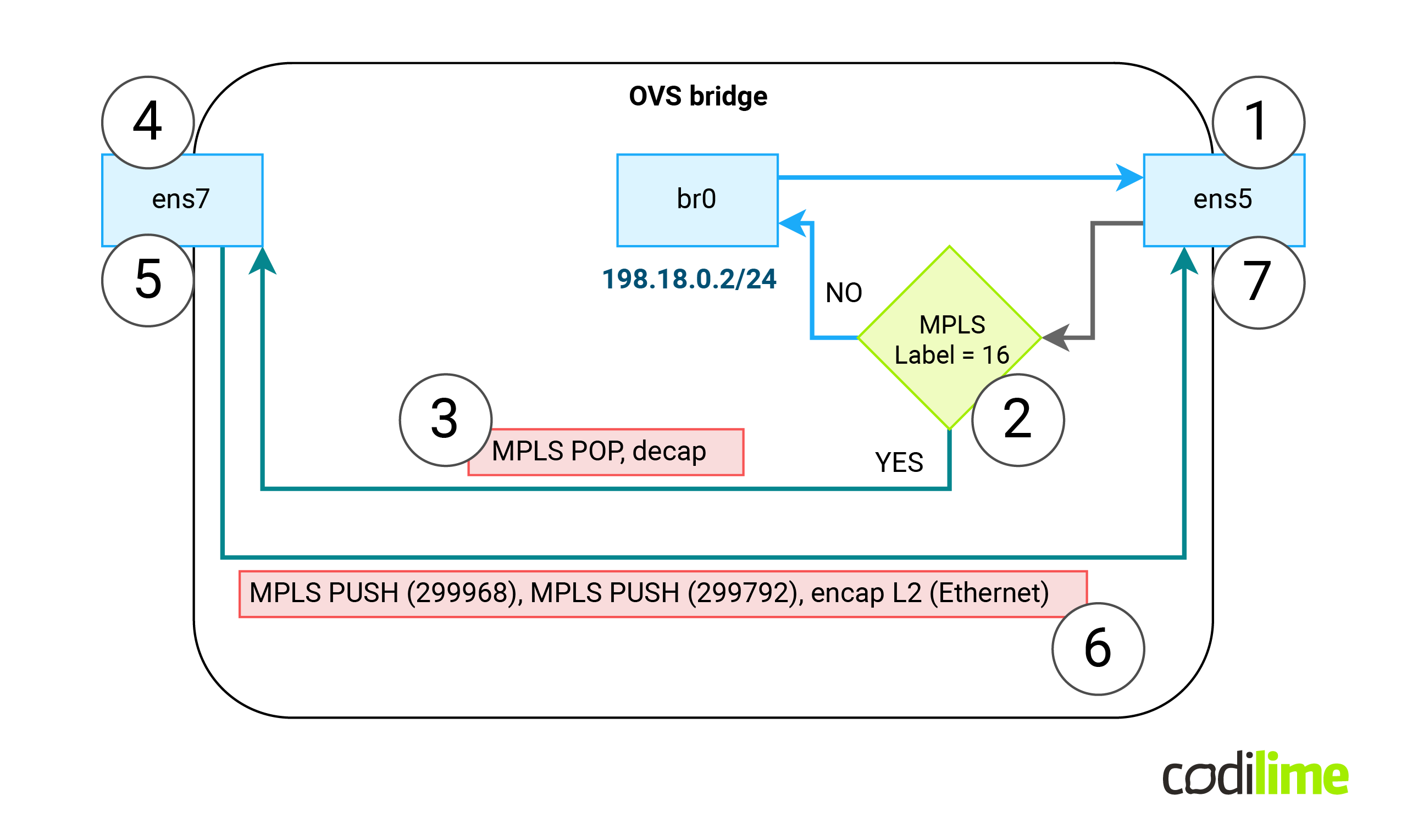
- If we receive a packet on ens5 (1) with MPLS label 16 (2) , we should remove that label, remove external Ethernet header (3) and forward the payload to the ens7 interface (4).
- If we receive a packet on ens7 interface (5), we need to perform L2 encapsulation and then push two MPLS labels (299968 & 299792) into the external Ethernet header, set new MAC src and DST for that external header (6) and push the packet using ens5 interface (7).
Note: on multiple main pages one can find information that OVS can only support an L3 payload inside an MPLS frame. Luckily this information is outdated and no longer valid.
Note: Since OVS is not aware of a control word (and has no support for it) - we previously prohibited the control word in MPLS packets by using a specific FRR config.
Using the above data, let’s create two OVS Openflow rules to encapsulate and encapsulate traffic:
root@FRR-PE:~# ovs-ofctl add-flow -O OpenFlow13 br0 "priority=101,in_port=ens5,dl_type=0x8847,mpls_label=16 actions=decap(),decap(packet_type(ns=0,type=0)),output:ens7"
root@FRR-PE:~# ovs-ofctl add-flow -O OpenFlow13 br0 "priority=100,in_port=ens7 actions=encap(mpls),set_mpls_label:299968,encap(mpls),set_mpls_label:299792,encap(ethernet),set_field:0c:d4:ac:6c:00:01->dl_src,set_field:0c:de:2f:94:00:01->dl_dst,output:ens5"
Verification
To check our solution thoroughly, on CE-L2 (which is attached to ens7 on FFR-PE) we created a kernel bridge (ce-br) with an eth0 interface attached to it (by default Linux creates an IRB-type interface and names its after the bridge name - here: ce-br). This will allow us to generate STP frames that should be carried by the VPWS as well (to check if multicast frames will be forwarded as well here ![]() ):
):
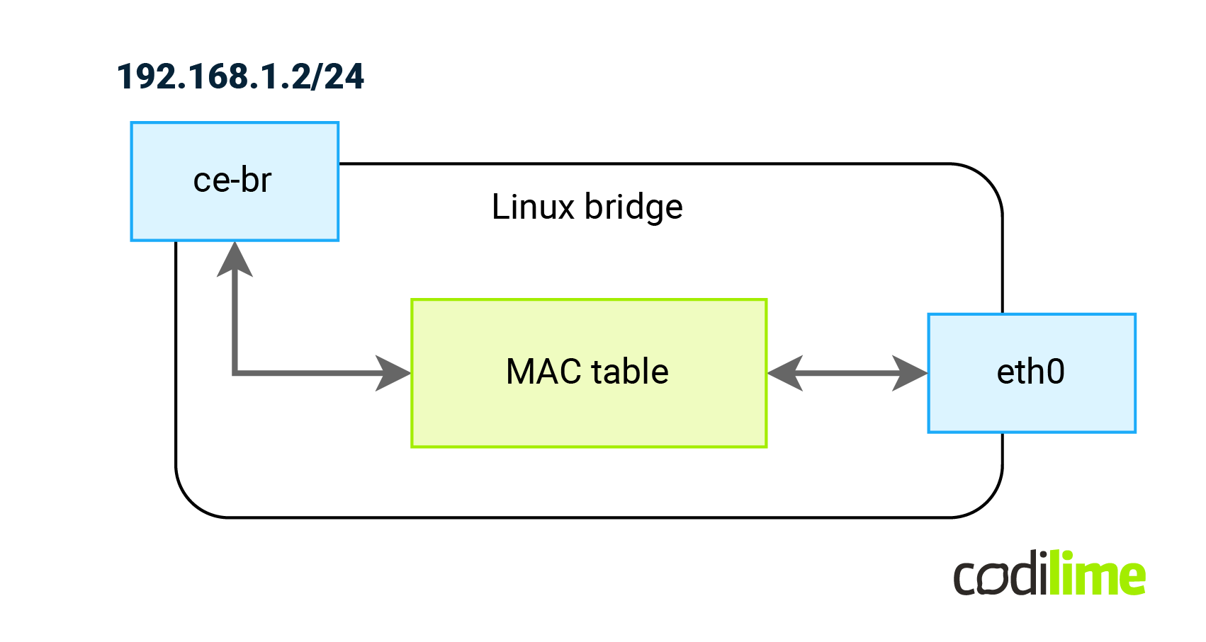
ce-l2:~# brctl addbr ce-br
ce-l2:~# brctl stp ce-br on
ce-l2:~# brctl addif ce-br eth0
ce-l2:~# ip l set ce-br up
ce-l2:~# ip address add 192.168.1.2/24 dev ce-br
At this point the communication between CEs will be as follows:
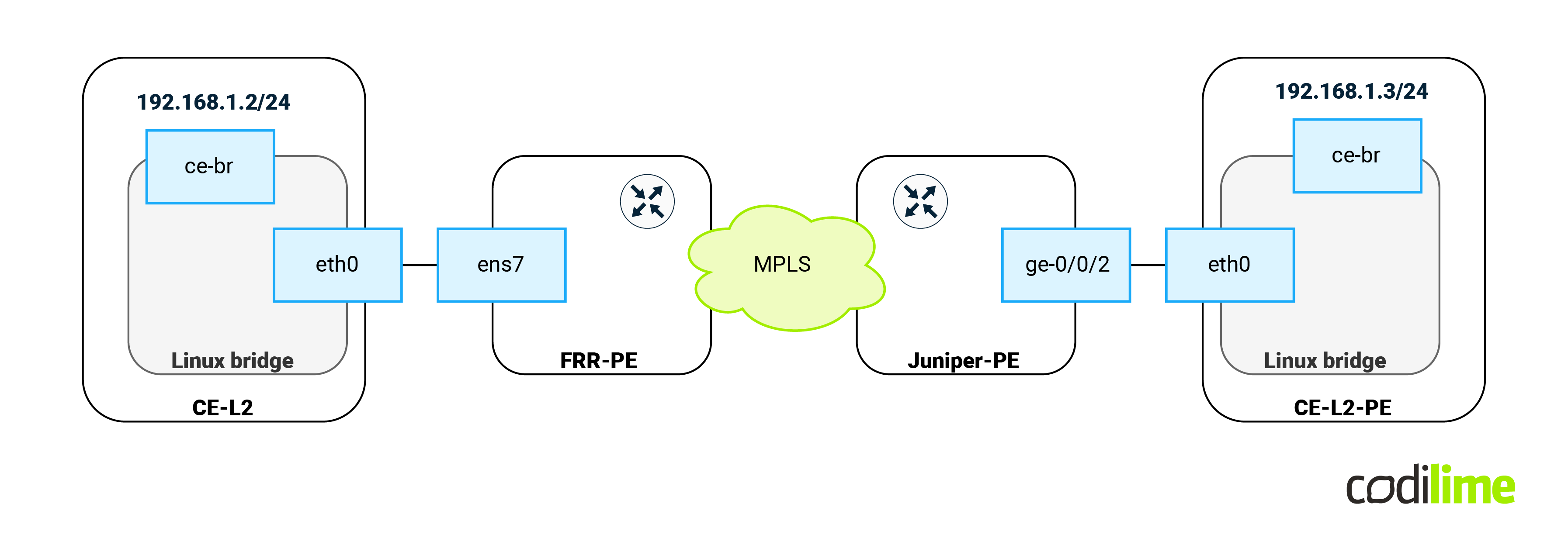
The same steps but with different IP (192.168.1.3/24) were performed on the opposite CE-L2-PE machine (attached to the Juniper PE device). Next we performed an ICMP ping between CEs:
ce-l2:~# ping -c 4 192.168.1.3
PING 192.168.1.3 (192.168.1.3): 56 data bytes
64 bytes from 192.168.1.3: seq=0 ttl=64 time=6.755 ms
64 bytes from 192.168.1.3: seq=1 ttl=64 time=3.561 ms
64 bytes from 192.168.1.3: seq=2 ttl=64 time=3.252 ms
64 bytes from 192.168.1.3: seq=3 ttl=64 time=3.758 ms


--- 192.168.1.3 ping statistics ---
4 packets transmitted, 4 packets received, 0% packet loss
round-trip min/avg/max = 3.252/4.331/6.755 ms
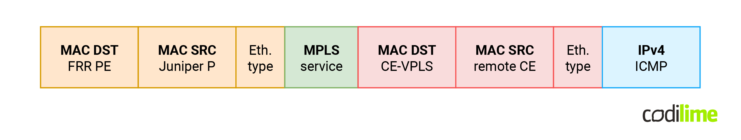
Since the ping was successful, let's concentrate on the MPLS labels that we expect to be found in transit. As usual we will capture traffic between FRR-PE and Juniper-P devices. The following diagram shows us the expected labels:
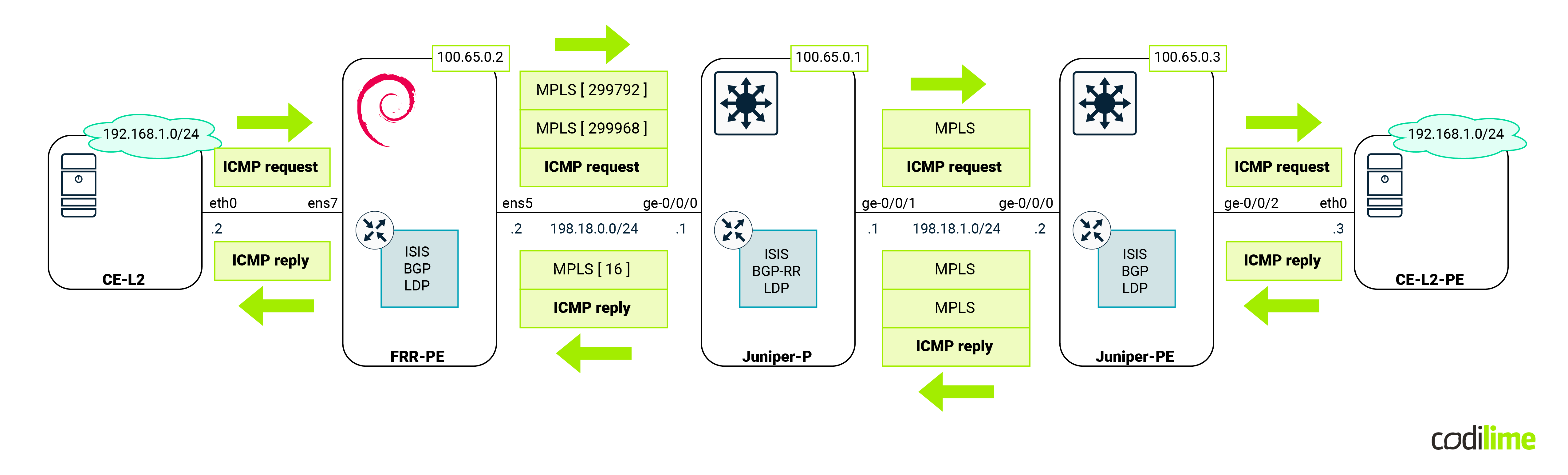
As we can see from the capture, traffic from FRR-PE is encapsulated twice (double PUSH):
Return traffic towards FRR-PE has single MPLS encapsulation, with the expected MPLS label.
The following output shows us Spanning Tree status on CE-L2. We can see here that the bridge-id (pointing to our MAC) and designated root (pointing to the remote CE MAC - see the above Wireshark outputs) are different. This is the proof that STP packets were properly sent via VPWS and that our solution is fully transparent to all Ethernet frames:
ce-l2:~# brctl showstp ce-br
ce-br
bridge id              8000.0ce5ccca0000
designated root        8000.0ca1b03c0000
root port                 1                    path cost                  2
max age                  20.00                 bridge max age            20.00
hello time                2.00                 bridge hello time          2.00
forward delay            15.00                 bridge forward delay      15.00
ageing time             300.00
hello timer               0.00                 tcn timer                  0.00
topology change timer     0.00                 gc timer                 177.61
flags


eth0 (1)
port id                8001                    state                forwarding
designated root        8000.0ca1b03c0000       path cost                  2
designated bridge      8000.0ca1b03c0000       message age timer         18.31
designated port        8001                    forward delay timer        0.00
designated cost           0                    hold timer                 0.00
flags
VPLS
According to Wikipedia’s definition, a VPLS (virtual private LAN service) “is a way to provide Ethernet-based multipoint to multipoint communication over IP or MPLS networks. It allows geographically dispersed sites to share an Ethernet broadcast domain by connecting sites through pseudowires. The term ‘sites’ includes multiplicities of both servers and clients. The technologies that can be used as pseudo-wire can be Ethernet over MPLS, L2TPv3 or even GRE. There are two IETF standards-track RFCs (RFC 4761[1] and RFC 4762)[2] describing VPLS establishment.”. Since Ethernet LAN communication is provided, full mesh connectivity over VPWS is required. As before, there two ways to achieve such goals in network equipment configuration:
- Using the BGP protocol (not supported in FRR)
- Using the LDP protocol (supported by FRR)
Aside from setting up VPWS, a VPLS adds to the features that we need to implement:
- Split horizon - to prohibit any traffic being switched back between two remote sites. So if anything comes over VPWS it must be sent towards the local interface.
- MAC learning - to keep BUM traffic at minimum. Traffic from the local CE device must be encapsulated into one VPWS tunnel based on previous incoming traffic. Just like in the classic L2 switch.
Since VPWS (and as a result VPLS) is not supported by the Linux kernel, we will have to implement those two extra features as well using OVS. First let's concentrate on the control plane. The following sections will cover the Juniper PE as well as Linux FRR configuration. Later we will concentrate on getting the data plane working. At the end we will perform verification by sending custom traffic and capturing that traffic on connection between Linux and the P router. That capture should show us properly encapsulated traffic.
Juniper
Note: In this topology Juniper P will be acting as PE and terminate VPLS by itself. This is done to achieve more than two sites (and more than a single VPWS) in the topology. P’s config and status is symmetrical to Juniper PE.
Juniper PE config:
root@Juniper-PE> show configuration routing-instances blog_vpls
instance-type vpls;
protocols {
   vpls {
       neighbor 100.65.0.1;
       neighbor 100.65.0.2;
       no-tunnel-services;
       vpls-id 100;
   }
}
interface ge-0/0/3.0;


root@Juniper-PE> show configuration interfaces ge-0/0/3
encapsulation ethernet-vpls;
unit 0 {
 family vpls;
}
Juniper PE status:
root@Juniper-PE> show vpls connections
[...]
Instance: blog_vpls
 VPLS-id: 100
   Neighbor                  Type  St     Time last up          # Up trans
   100.65.0.1(vpls-id 100)   rmt   Up     Sep 26 08:53:11 2023           1
     Remote PE: 100.65.0.1, Negotiated control-word: No
     Incoming label: 262145, Outgoing label: 262146
     Negotiated PW status TLV: No
     Local interface: lsi.1049091, Status: Up, Encapsulation: ETHERNET
       Description: Intf - vpls blog_vpls neighbor 100.65.0.1 vpls-id 100
     Flow Label Transmit: No, Flow Label Receive: No
   100.65.0.2(vpls-id 100)   rmt   Up     Sep 26 12:12:52 2023           1
     Remote PE: 100.65.0.2, Negotiated control-word: No
     Incoming label: 262146, Outgoing label: 18
     Negotiated PW status TLV: No
     Local interface: lsi.1049094, Status: Up, Encapsulation: ETHERNET
       Description: Intf - vpls blog_vpls neighbor 100.65.0.2 vpls-id 100
     Flow Label Transmit: No, Flow Label Receive: No
FRR-PE config:
FRR-PE# show running-config
[...]
l2vpn blog_vpls type vpls
!
member pseudowire pw1
 neighbor lsr-id 100.65.0.1
 pw-id 100
 control-word exclude
exit
!
member pseudowire pw2
 neighbor lsr-id 100.65.0.3
 pw-id 100
 control-word exclude
exit
!
exit
!
FRR-PE status:
FRR-PE# show mpls pseudowires detail
[...]
Interface: pw1
 Neighbor: 100.65.0.1
 Local Label: 17
 Remote Label: 262145
 Protocol: ldp
 VC-ID: 100
 Status: Up
 Next Hop: 198.18.0.1, via br0
 Next Hop label: 3
Interface: pw2
 Neighbor: 100.65.0.3
 Local Label: 18
 Remote Label: 262146
 Protocol: ldp
 VC-ID: 100
 Status: Up
 Next Hop: 198.18.0.1, via br0
 Next Hop label: 299792
Note: for the first VPWS there is a next hop label equal to 3. This is a so-called implicit null label and it shows that the P Juniper router wants to receive MPLS packets only with service labels attached (in that case, the preceding router performs an action called PHP - penultimate hop popping and removes the transport label before sending the packet further).
Linux
We already covered how to achieve VPWS in the Linux kernel using OVS. As mentioned earlier, in VPLS we must also implement split horizon features and MAC learning. Let's concentrate on the latter. For MAC learning to work, the mechanism must operate on the payload (internal, red header in the diagram below) MAC addresses. In other words, based on the incoming MPLS traffic, the learning process must create reverse rules. As a result, when a local host responds, its traffic will be encapsulated within a proper VPWS tunnel (with the exception of unknown unicast which we will cover as well) based on the reverse rules created earlier.
This is how the VPLS packet will look when appearing on the ens5 interface:
When trying to remove external headers in OVS (orange) and implement learning on payload (red headers) immediately one problem appears. Even after removing an external header from incoming MPLS frames (MPLS POP and decap actions - removing orange and green headers), all OVS fields used to match incoming packets (eth_src and eth_dst) still have the values from the external (orange) headers and not from the internal (red) as one would expect. In other words, the header removal action (decapsulate packet) does not update eth_src / eth_dst headers. Even worse, OVS also has no way to access the MAC addresses of internal header packets (red). As a result, this blocks us from implementing MAC learning based on the internal header in a single run (one OVS rule). We have to match the incoming packet twice. At this point we have two options:
-
Use kernel “veth” interfaces and create a topology like this:
Fig.16: OVS configuration with Linux bridge in VPLS scenario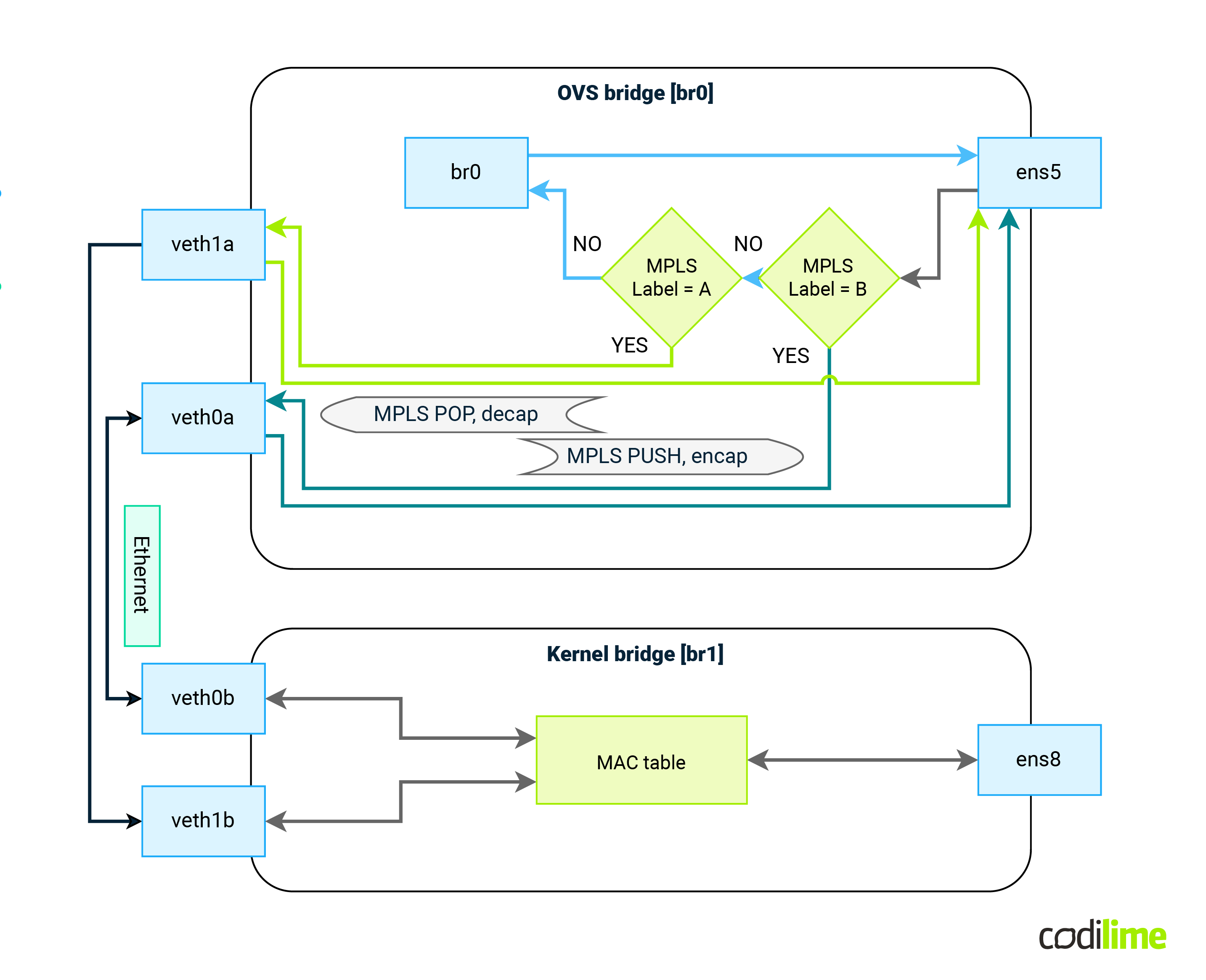
Incoming traffic flow will be as follows:
- Packet enters via ens5
- Match incoming packet based on MPLS label
- Remove MPLS labels, remove external Ethernet header
- Based on MPLS label value, send packet via corresponding veth interface
- Packet leaves OVS and enters kernel bridge via other veth endpoint
- Classical MAC learning/forwarding on the bridge does the rest
Outgoing traffic flow will be as follows:
- Packet enters via ens8
- Based on previous MAC learning, packet is sent via correct veth interface
- Packet leaves kernel bridge and appears in OVS bridge
- Based on incoming interface packet is encapsulated into new Ethernet header
- Correct MPLS label(s) are added to that packet
- MAC addresses of external header are set
- Packet leaves via ens5 interface
-
Use OVS patch interfaces (patch interface is like lt-x/x/x in Juniper - connect bridges using p2p virtual link):
- A similar solution as before (one pair of patch interfaces for each VPWS instead of veth pairs).
- Create a second bridge domain in OVS (with ens8 attached to it).
- Implement MAC learning along with split horizon there by using custom OVS rules.
The first solution (with the kernel bridge) although easier to implement has one major flaw. As soon as the internal packet reaches the Linux bridge, nothing prohibits it from going back to the MPLS network via a different veth interface. At the Linux bridge there is no easy way to implement split horizon.
The second solution gives us more flexibility with what to do with packets after external headers have been removed. Also, the “patch” interface type is an internal OVS type of interface, which means we are not switching context between kernel and OVS (which improves performance).
At this point the solution should look like the one presented in the diagram below:
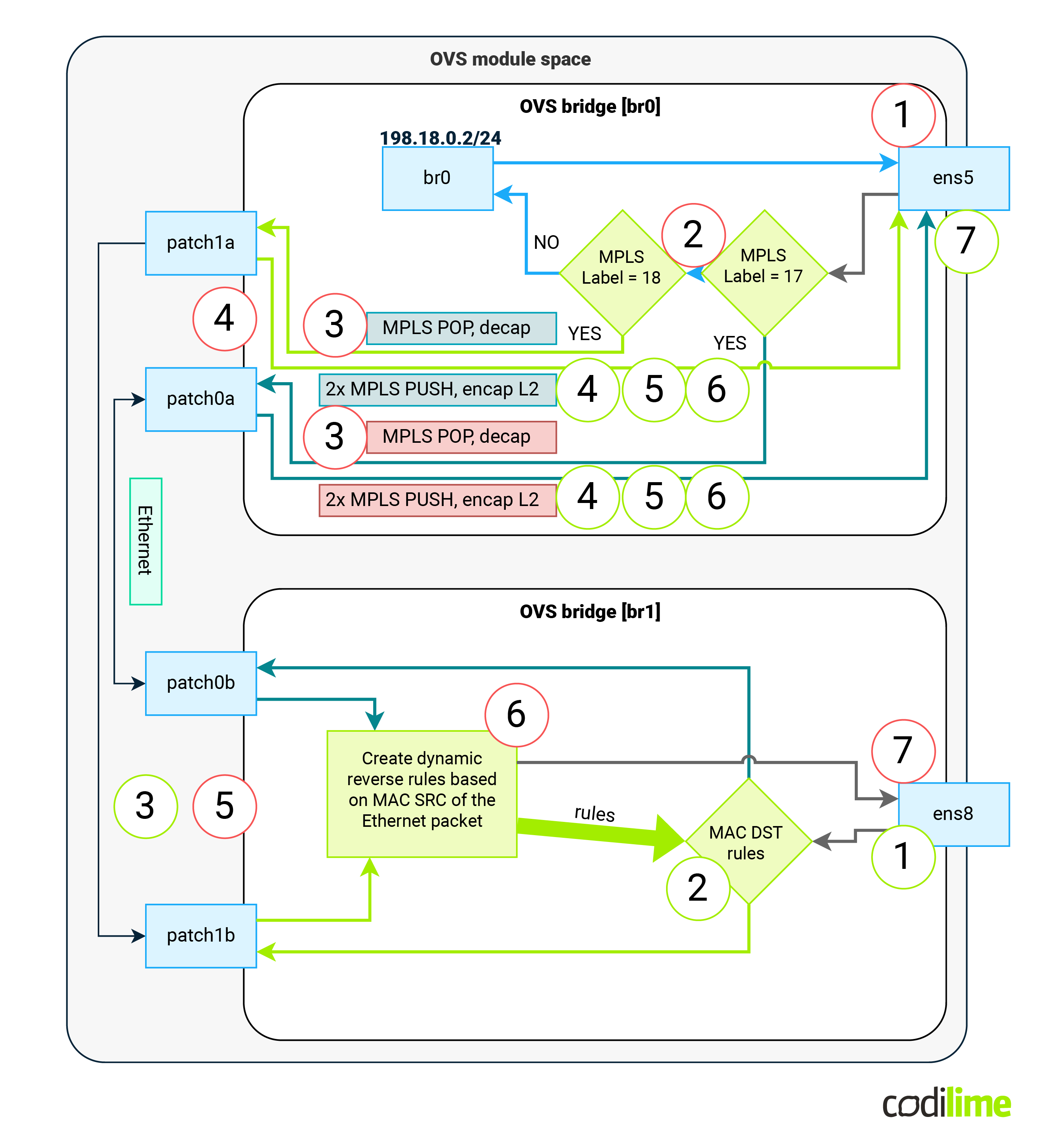
Steps for incoming traffic will be as follows (red-circled numbers):
-
Packet enters via ens5
-
Match incoming packet based on MPLS label
-
Remove MPLS labels and remove external Ethernet header
-
Based on MPLS label value, send packet via corresponding patch interface
-
Packet leaves OVS br0 and enter OVS br1 corresponding patch endpoint
-
Dynamically create reverse rule that:
- Will compare DST MAC of return packet with SRC MAC of current packet
- If there is a match, sends that packet to the patch interface on which the current packet was received
- If there is no match, continue with next dynamic rule
-
Sent packet directly to ens8 interface
Outgoing traffic flow will be as follows:
-
Packet enters via ens8
-
Packet is subjected to dynamic rules created in previous step 6.
- If there is a match - send the packet via correct patch interface
- If there is no match - send the packet via all patch interfaces
-
Packet leaves OVS br1 and appears in OVS br0
-
Based on incoming patch interface packet is encapsulated into new Ethernet header
-
Correct MPLS label(s) are added to that packet
-
MAC addresses of external header are set
-
Packet leaves via ens5 interface
Let's implement those steps:
First we should create the necessary interfaces and second OVS bridge:
root@FRR-PE:~# ip l add pw1 type dummy
root@FRR-PE:~# ip l add pw2 type dummy
root@FRR-PE:~# ip l set up pw1
root@FRR-PE:~# ip l set up pw2
root@FRR-PE:~# ovs-vsctl add-port br0 pw1
root@FRR-PE:~# ovs-vsctl add-port br0 pw2
root@FRR-PE:~# ovs-vsctl add-br br1
root@FRR-PE:~# ovs-ofctl del-flows br1
root@FRR-PE:~# ovs-vsctl add-port br1 ens8
Now we should connect those two bridges together using patch-type interfaces:
root@FRR-PE:~# ovs-vsctl add-port br0 patch0a -- set interface patch0a type=patch options:peer=patch0b
root@FRR-PE:~# ovs-vsctl add-port br1 patch0b -- set interface patch0b type=patch options:peer=patch0a
root@FRR-PE:~# ovs-vsctl add-port br0 patch1a -- set interface patch1a type=patch options:peer=patch1b
root@FRR-PE:~# ovs-vsctl add-port br1 patch1b -- set interface patch1b type=patch options:peer=patch1a
Based on FRR info (and MAC addresses from the VPWS section) we can prepare MPLS rules for incoming and outgoing traffic (those rules will match based on MPLS label value, strip headers/labels and send packet via patch interface):
root@FRR-PE:~# ovs-ofctl add-flow -O OpenFlow13 br0 "priority=100,in_port=ens5,dl_type=0x8847,mpls_label=17 actions=decap(),decap(packet_type(ns=0,type=0)),output:patch0a"
root@FRR-PE:~# ovs-ofctl add-flow -O OpenFlow13 br0 "priority=100,in_port=ens5,dl_type=0x8847,mpls_label=18 actions=decap(),decap(packet_type(ns=0,type=0)),output:patch1a"
root@FRR-PE:~# ovs-ofctl add-flow -O OpenFlow13 br0 "priority=100,in_port=patch0a actions=encap(mpls),set_mpls_label:262145,encap(ethernet),set_field:0c:d4:ac:6c:00:01->dl_src,set_field:0c:de:2f:94:00:01->dl_dst,output:ens5"
root@FRR-PE:~# ovs-ofctl add-flow -O OpenFlow13 br0 "priority=100,in_port=patch1a actions=encap(mpls),set_mpls_label:262146,encap(mpls),set_mpls_label:299792,encap(ethernet),set_field:0c:d4:ac:6c:00:01->dl_src,set_field:0c:de:2f:94:00:01->dl_dst,output:ens5"
At this point, the packet is at the OVS br1 interface coming to it via a specific patchXX interface. All that is left is: MAC learning and the split horizon. Right now on the OVS bridge br1 any packet that comes via a patch interface will have headers that we can use in our rules (internal ones, after MPLS and external header removal - the red ones from the header drawing). At this point, we must act like a classic bridge with MAC learning but with one important exception: a packet appearing via patch interface will trigger MAC learning, but it will not be subject to the MAC table and it will be sent blindly to the ens8 interface. So we must create custom rules here as well. We need to add a special OVS rule that aside from sending that packet to CE (via ens8) must also create/update a MAC table that will be used for returning the packet. So we will have asymmetry in br1:
- Traffic from br0 (via patch) will not be subjected to a MAC table, but will trigger MAC learning and will be sent to ens8 blindly,
- Traffic from ens8 (from CE) will be a subject to a MAC table but will not trigger MAC learning.
That asymmetry will be achieved by using dynamic reverse rules creation that will be injected via the LEARN function that OVS offers (see this excellent OVS tutorial ![]() that explains this feature). Packet flooding will be done using OVS “output:flood” action. Having all that in our head, let's proceed with OVS OpenFlow rules:
that explains this feature). Packet flooding will be done using OVS “output:flood” action. Having all that in our head, let's proceed with OVS OpenFlow rules:
root@FRR-PE:~# ovs-ofctl add-flow -O OpenFlow15 br1 "priority=100,in_port=patch0b actions=learn(priority=10,table=0,idle_timeout=300,NXM_OF_ETH_DST[]=NXM_OF_ETH_SRC[],output:NXM_OF_IN_PORT[]),output:ens8"
root@FRR-PE:~# ovs-ofctl add-flow -O OpenFlow15 br1 "priority=100,in_port=patch1b actions=learn(priority=10,table=0,idle_timeout=300,NXM_OF_ETH_DST[]=NXM_OF_ETH_SRC[],output:NXM_OF_IN_PORT[]),output:ens8"
root@FRR-PE:~# ovs-ofctl add-flow -O OpenFlow15 br1 "priority=0,in_port=ens8 actions=output:flood"
At this point, all that is left is verification if our solution works.
Verification
An ICMP ping was sent between two VLPS-CE devices attached to FRR-PE and Juniper-P:
ce-vpls:~# ping -c 4 192.168.42.1
PING 192.168.42.1 (192.168.42.1): 56 data bytes
64 bytes from 192.168.42.1: seq=0 ttl=64 time=5.381 ms
64 bytes from 192.168.42.1: seq=1 ttl=64 time=2.384 ms
64 bytes from 192.168.42.1: seq=2 ttl=64 time=2.805 ms
64 bytes from 192.168.42.1: seq=3 ttl=64 time=2.234 ms


--- 192.168.42.1 ping statistics ---
4 packets transmitted, 4 packets received, 0% packet loss
round-trip min/avg/max = 2.234/3.201/5.381 ms
We can see that ICMP communication is working properly, so let's see what is happening under the hood. Before an ICMP packet is sent, the CE device must issue an ARP request. We expect the following communication:
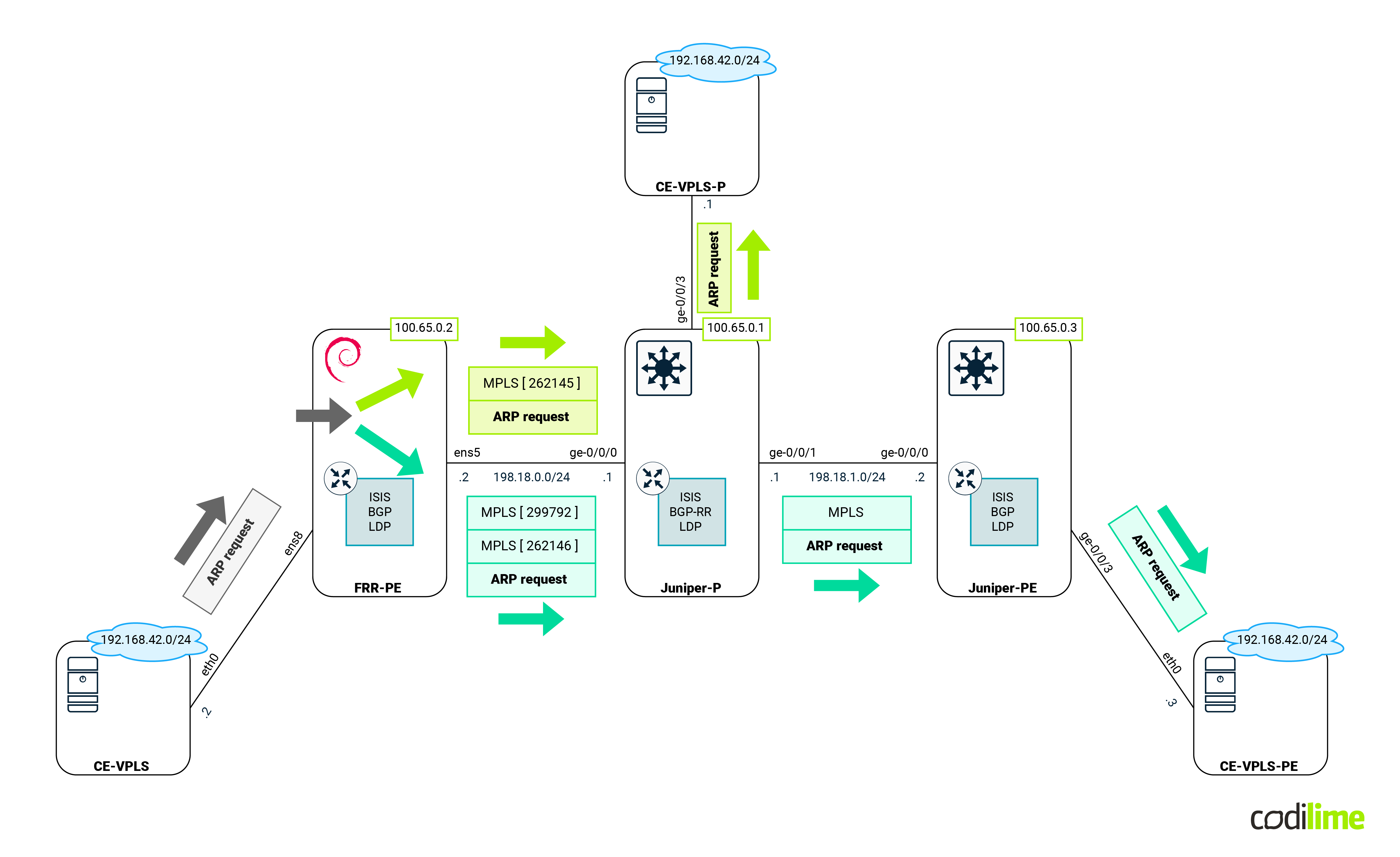
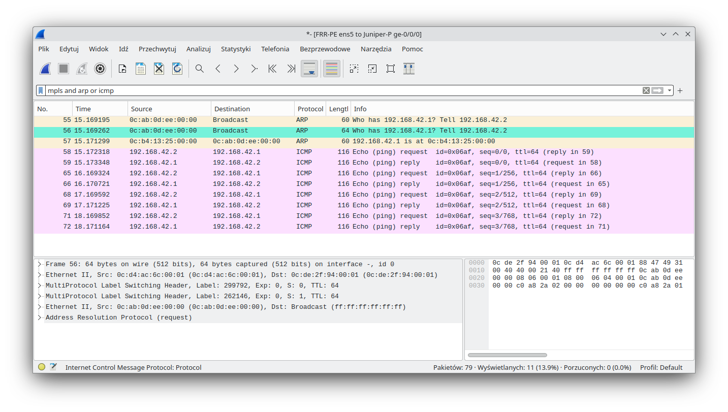
As we can see, an ARP request is sent to both endpoints with the proper labels (proper VPWS). Towards the Juniper-P CE:
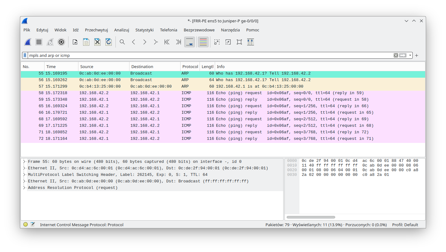
And towards the Juniper-PE CE:
While we are checking ARP/MACs, we should also look to see if our MAC learning and split horizon features are working as expected. This is the dynamic reverse table on FRR-RE after packets were exchanged:
root@FRR-PE:~# ovs-ofctl -O openflow15 dump-flows br1 cookie=0x0, duration=50.293s, table=0, n_packets=6, n_bytes=476, idle_age=2, priority=100,in_port=patch0b actions=learn(table=0,idle_timeout =300,priority=10,NXM_OF_ETH_DST[]=NXM_OF_ETH_SRC[],output:NXM_OF_IN_PORT[]),output:ens8 cookie=0x0, duration=50.254s, table=0, n_packets=0, n_bytes=0, idle_age=50, priority=100,in_port=patch1b actions=learn(table=0,idle_timeout= 300,priority=10,NXM_OF_ETH_DST[]=NXM_OF_ETH_SRC[],output:NXM_OF_IN_PORT[]),output:ens8 cookie=0x0, duration=50.212s, table=0, n_packets=1, n_bytes=42, idle_age=7, priority=0,in_port=ens8 actions=FLOODcookie=0x0, duration=7.462s, table=0, n_packets=5, n_bytes=434, idle_timeout=300, idle_age=2, priority=10,dl_dst=0c:b4:13:25:00:00 actions=output:patch0b
We can clearly see that MAC for remote CE 0c:b4:13:25:00:00 is related to interface patch0b (which corresponds to VPWS that points to Juniper-P).
Summary
In this somewhat lengthy blog entry we have shown that Linux is capable of participating in ISP/Telco services such as L3VPN, VPWS or VPLS. What is important is that we used native kernel modules, so the same functions should be available on x86 servers as well as on ARM devices (IoT). However one should keep in mind that for VPLS and VPWS our PoC was static and as soon as an MPLS label changes, our configuration would have to be updated. Unfortunately FRR offers poor automation capabilities (this is slowly changing with the 9.0 release). Also the LDP protocol that we used does not scale well. A solution for both those problems would be to use GoBGP along with a labeled-unicast family and l2vpn family - GoBGP has an excellent API to provide automation but that is a story for another blog post.
>> Read more about our network professional services.


