


Data center architectures are necessary to provide both enterprises and service providers with the required infrastructure to host any type of consumer service. From compute servers to content delivery networks, data center networking includes various connectivity solutions crucial for a seamless service ecosystem.
To meet the demands of modern networking, data center networks must prioritize key features such as robust network bandwidth, high availability, scalability, and stringent security measures.
In this article, we compare two solutions: traditional data centers architecture and the spine-leaf architecture.
The core of data centers
Data center architectures have been a part of the computer networking ecosystem for dozens of years now. Encompassing diverse connectivity solutions from compute servers, databases, voice over IP (VoIP) solutions, content delivery networks (CDNs), etc. - data center networking is a core part of any enterprise or service provider network.
A data center network must offer a couple of key features in order to ensure the proper resources for the services ecosystem that it supports:
-
Network bandwidth - especially for east-west traffic requirements. A lot of traffic in a data center is east-west and the majority of it should be contained within the data center.
- Note: east-west traffic represents the traffic between servers/applications within the data center while north-south traffic represents traffic that is going towards/from the datacenter (i.e. leaving/entering the data center).
-
High availability / resiliency - each component in the data center must be highly available and resilient. Starting from local link resiliency to redundant power supplies and traffic processors, each component must be designed and deployed with resiliency in mind.
-
Scalability - the network itself must be able to scale fast - especially horizontally. Operations like adding a new top of the rack (TOR) switch should be simple and straightforward.
-
Security - last but not least, security is an extremely important factor that must be taken into consideration when designing a data center. From physical security to disk encryption and protocol authentication, access to the data center network must be locked down, restricted to authorized personnel only.
Traditional data center networks
Traditionally - data center networking was based around layer 2 connectivity - using layer 2 switches for the most part and at least one pair (for high availability) of layer 3 devices - commonly routers and/or firewalls in some cases.
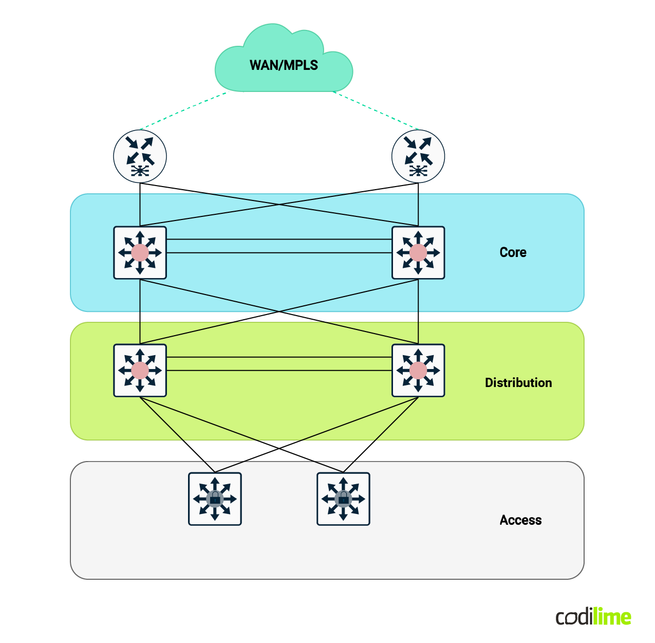
The above architecture is commonly called 3-tier architecture - or core-aggregation-access. This is one of the first standard architectures that remains in wide use today and still offers some basic functionality.
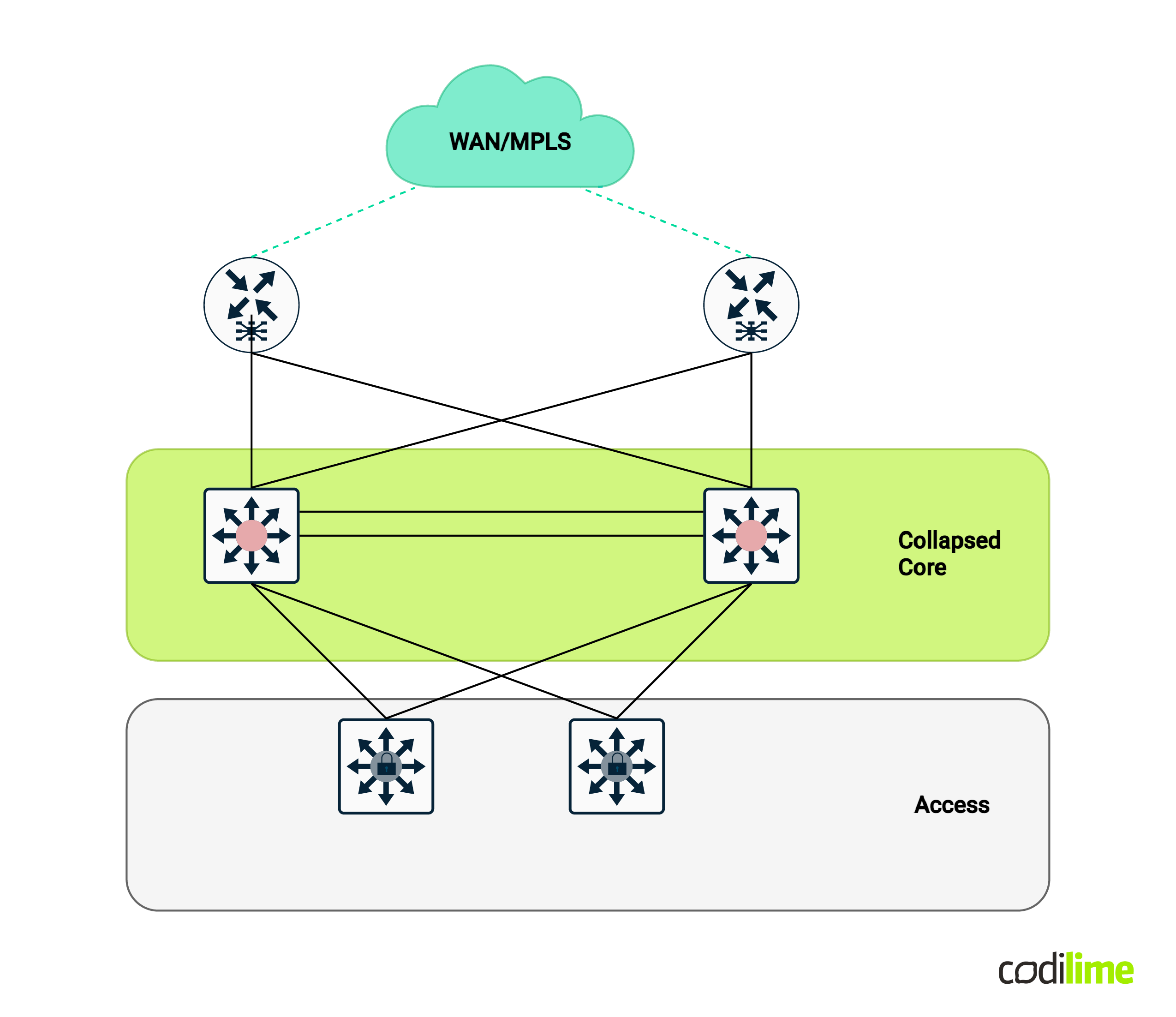
Another variation of this architecture is called the collapsed core design - in which the core and distribution (aggregation) layers are combined into one:
Due to the rapid evolution of networking connectivity requirements, segmenting the network based on virtual local area network (VLAN) tags became an issue (limited VLAN numbers, relying on STP for loop assurance, etc.) Furthermore, layer 2 technologies also bring to the table a list of important issues for network operations that can easily bring down your entire data center network if not properly mitigated: layer 2 loops, lack of load balancing, spanning tree protocol (STP) convergence, broadcast storm, etc. Layer 3 technologies are not prone to these many issues and are usually the preferred option when talking about networking connectivity.
Nonetheless, there are still some solutions that require a broadcast domain (layer 2 connectivity) between servers/applications for various reasons or legacy solution compatibility/interworking. So while there is still a need for this layer 2 connectivity, a layer 3 approach to this type of architecture would bring a lot of benefits!
Enter the Matrix…I mean IP Fabric!
Next-generation spine-leaf IP Fabric data center
IP Fabric data centers based on spine-leaf architecture have been around for a couple of years now and are considered a mature and stable technology. The main concept behind this architecture is to have predictable network connectivity parameters based on layer 3 technologies that avoid a lot of the issues found in legacy data centers.
Please note that from this point forward the terms IP Fabric and spine-leaf architecture are interchangeable because we are referring specifically to the leaf and spine topology from the IP Fabric spectrum.
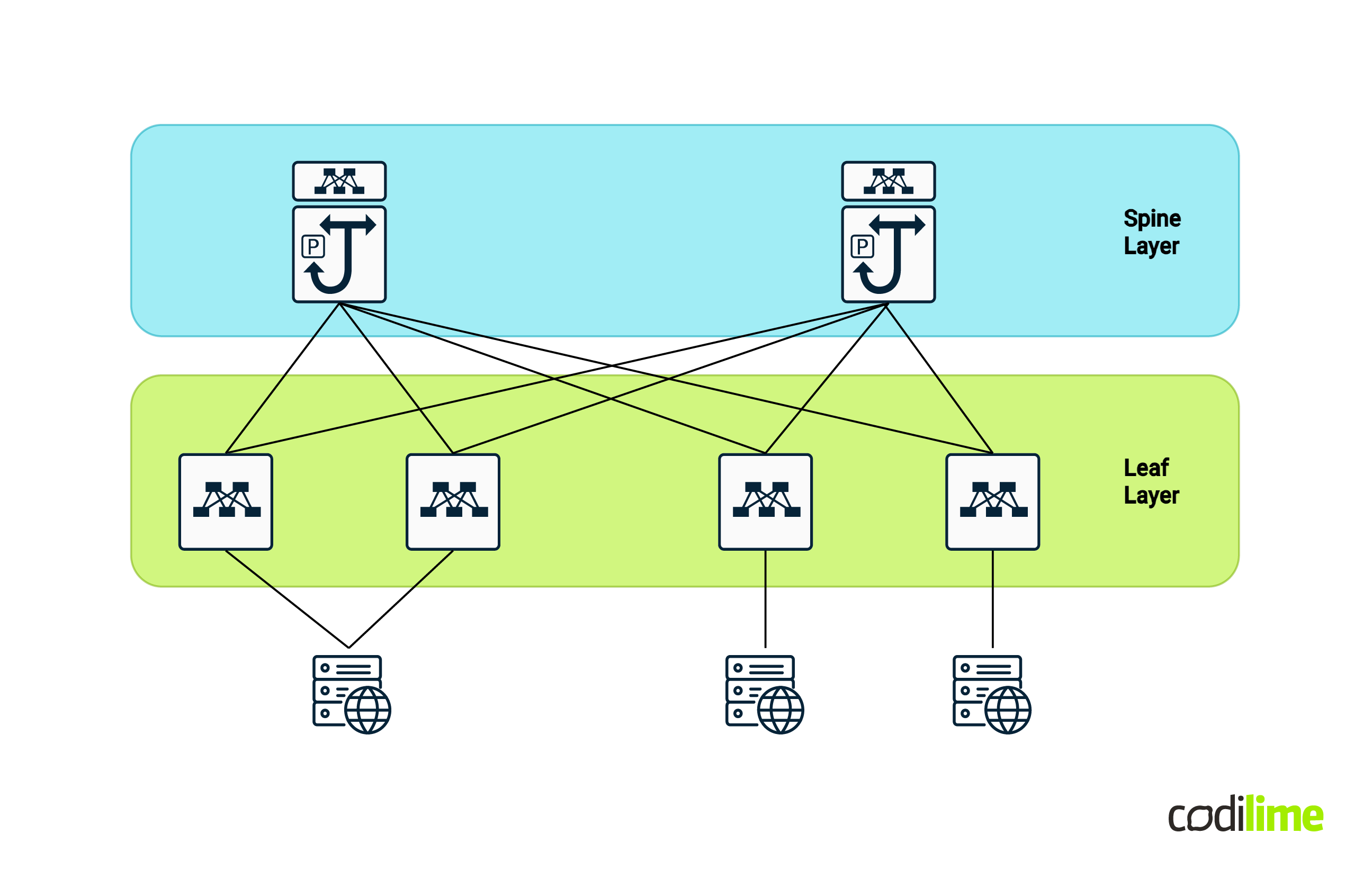
A spine-leaf topology is based on a Clos network architecture (first formalized by the American engineer Charles Clos in 1952). In it we have two main layers (although some scalable scenarios have evolved further from this two-layer standard - like super-spine architecture):
- The spine layer - usually composed of at least two layer 3 high throughput switches (two for redundancy purposes)
- The leaf layer - usually composed of N layer 3 feature-rich switches, where N can be any number (usually an even number, also for redundancy, and as high as possible as long as there are enough ports on the spines to connect them to).
The main characteristic of the Clos network and thus the spine-leaf architecture is that all of the leafs are connected to all of the spines and there is (usually) no direct connection between the leafs themselves.
Based on this architecture we can also easily calculate the number of required links using the following inputs :
- S = number of spines
- L = number of leafs
- CB = number of cables between a leaf and a spine
Total Number of Links = S x L x CB
If we take into account an example with:
- S = 4 , L = 8 and CB = 1
- Total number of links = 32 links
There are quite a few spine-leaf technologies out in the market from different vendors - some are proprietary (like Cisco ACI) and some are also standards-based (like BGP EVPN with VXLAN encapsulation - you can find more information in our blog post explaining Ethernet VPNs.
In alignment with prevailing industry standards, from now on we will be using BGP EVPN with VXLAN encapsulation as the IP Fabric solution of choice going forward with our analysis.
Let’s briefly describe the technologies referenced earlier for a better understanding of what we actually want to compare:
-
BGP EVPN (Border Gateway Protocol Ethernet virtual private network) is a networking technology and protocol suite designed for efficient and scalable multipoint Ethernet services in both provider and enterprise networks. BGP EVPN leverages the Border Gateway Protocol (BGP) as the control plane to distribute and manage MAC (media access control) addresses and IP address information in a way that supports the requirements of virtualized and cloud-based infrastructures. Some key features of BGP EVPN:
- Layer 2 and layer 3 multi-tenancy support - BGP EVPN is designed to support multiple tenants or customers in a shared network infrastructure, making it suitable for service providers and large enterprises with diverse networking requirements.
- EVPN multihoming is a great standards-based approach to proprietary MC-LAG technology variants. This allows for interoperability between different vendors' equipment, fostering a more diverse and flexible network environment.
- Support for both layer 2 and layer 3 services - BGP EVPN is able to advertise both MAC-IP NLRI (also known as EVPN route type 2) and full subnet NLRI (also known as EVPN route type 5); these two route types being the most common across EVPN use cases.
- It uses the concepts of route targets (RTs) and route distinguishers (RDs) for identification, classification and route filtering within the BGP EVPN fabric - concepts are exactly the same as found in MPLS (Multiprotocol Label Switching) L3 VPN and L2 VPN (with BGP signaling) networks. This specific feature allows for very scalable single leaf-spine BGP (MP-BGP) session deployments - in the sense that you do not have to configure back to back VRF (virtual routing and forwarding) BGP sessions if you want to achieve connectivity between devices for multiple tenants.
- Standards-based interoperability - BGP EVPN is standards based, so interoperability between different network vendors is possible.
-
VXLAN encapsulation: BGP EVPN often works in conjunction with the VXLAN encapsulation protocol to enable the creation of virtual layer 2 networks over a layer 3 infrastructure. VXLAN helps overcome the limitations of traditional VLANs, allowing for a more scalable and flexible network design. VXLAN features include:
- Overlay network - encapsulates the original packet in a new MAC-in-IP header which completely “hides” the original information and enables packet crossing over a common data center network.
- Increased scalability - VXLAN uses a 24-bit identifier called the VXLAN network identifier (VNI) to extend VLANs and provide a much larger address space (16 million) compared to the 12-bit VLAN ID limit (4096) in traditional VLANs. This enables greater scalability in large and dynamic environments.
- Support for MAC-IP mobility - VXLAN enables support (along with BGP EVPN) for live VM migration (for example VMWare vMotion) within the datacenter but also cross-datacenter migration is possible as well.
- Standards-based interoperability - VXLAN (as BGP EVPN) is standards based - so interoperability between different network vendors is possible.
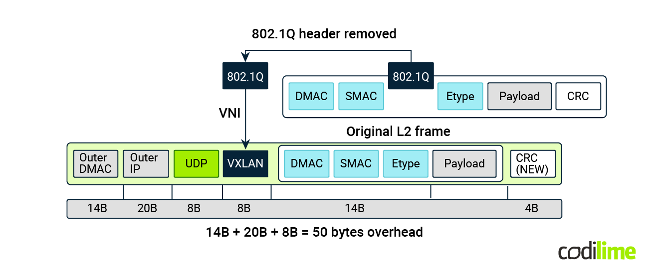
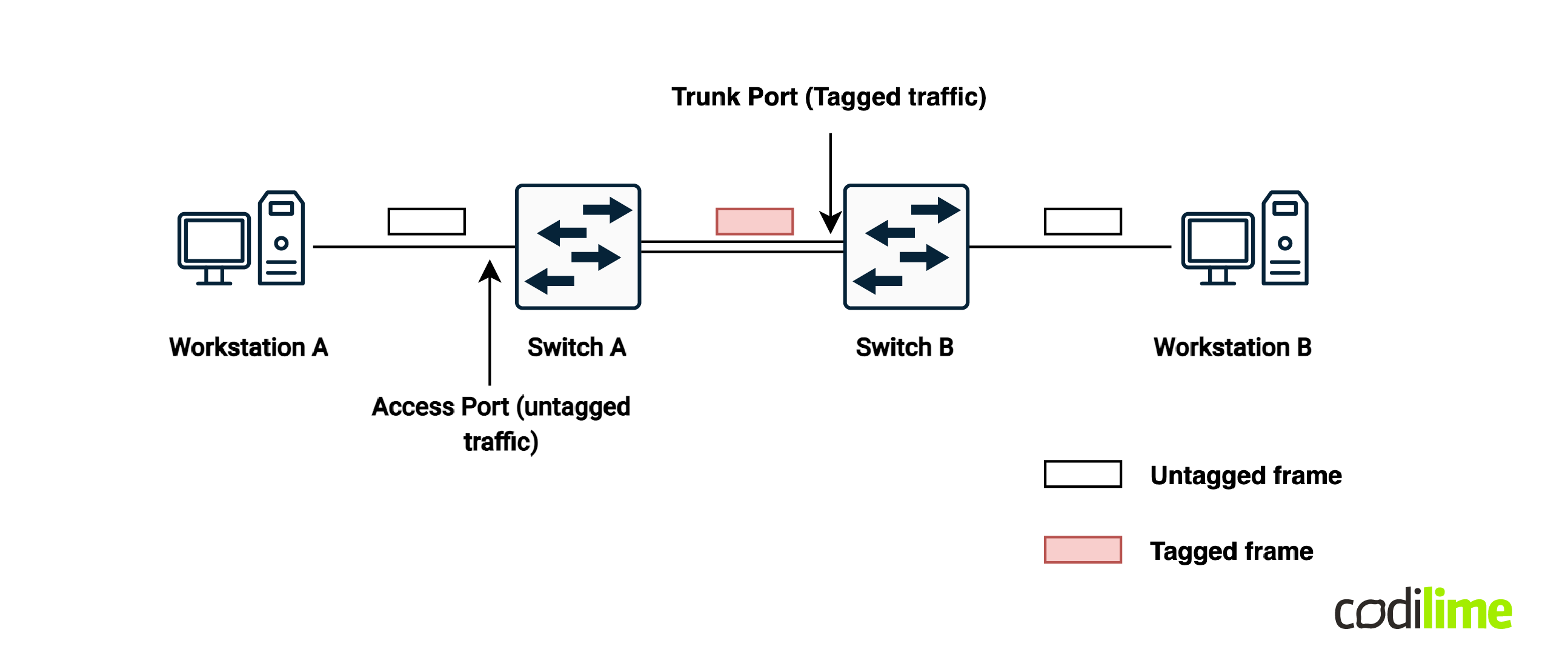
Just for reference, this is how a VXLAN header looks when VLAN to VNI (VXLAN network identifier) mapping takes place:
Before starting the comparison itself, let’s delve into how the two domain terminologies compare so we can get an even better grasp:
Table 1. Traditional DC and Spine Leaf comparison
| Traditional DC | Spine-leaf | |
|---|---|---|
| Multi-tenancy capabilities | layer 2 | Layer 2 + layer 3 |
| Logical segregation | VLAN | VXLAN* |
| MAC learning method | data plane | control plane |
| Overlay technology | N/A | VXLAN |
| BUM traffic handling | broadcast | multicast or ingress replication |
| Multi-site capabilities | layer 2 stretching | multi-site EVPN |
| Spanning-tree presence | in the entire L2 fabric | edge leaf only |
| External connectivity | layer 2 only | layer 2, Back-to-Back VRF, EVPN stretch |
| Microsegmentation | no | yes |
| Required MTU (based on standard untagged 1500-byte packet) | 1500 | 1550 |
* Although spine-leaf IP fabrics use VXLAN as their primary encapsulation within their backbone, VLAN tags are still used at the leaf access layer in order to properly interoperate with end devices such as servers. Servers and other compute infrastructure components rarely encompass advanced encapsulation such as VXLAN thus the requirement for such support on the networking edge components.
Now that we have a better understanding of the two main architectures, let’s try to compare them and see which design would match which scenario!
Traditional data center vs. spine-leaf IP Fabric
In order to properly compare the two architectures, we will be taking a closer look at the following characteristics for each one:
- Scalability,
- Convergence time,
- Multitenancy,
- Multi-path ECMP,
- Configuration complexity (knowledge ramp-up time),
- Programmability and automation,
- Hardware costs.
Before we start delving deeper into these intricacies, let’s go over a few comparisons of the concepts of the two architectures:
Scalability
Traditional layer 2 data center architecture is scalable up to a point. If we’re talking about a number of up to 100 servers (don’t take this number as an actual reference because a lot of factors come into this decision) it can do its job pretty decently. From a server perspective, we’re taking into consideration hypervisor servers that run a couple of hundred VMs - which means that at the switching Fabric itself we can have up to a couple of hundred or around a thousand virtual machine interfaces and their associated MAC addresses.
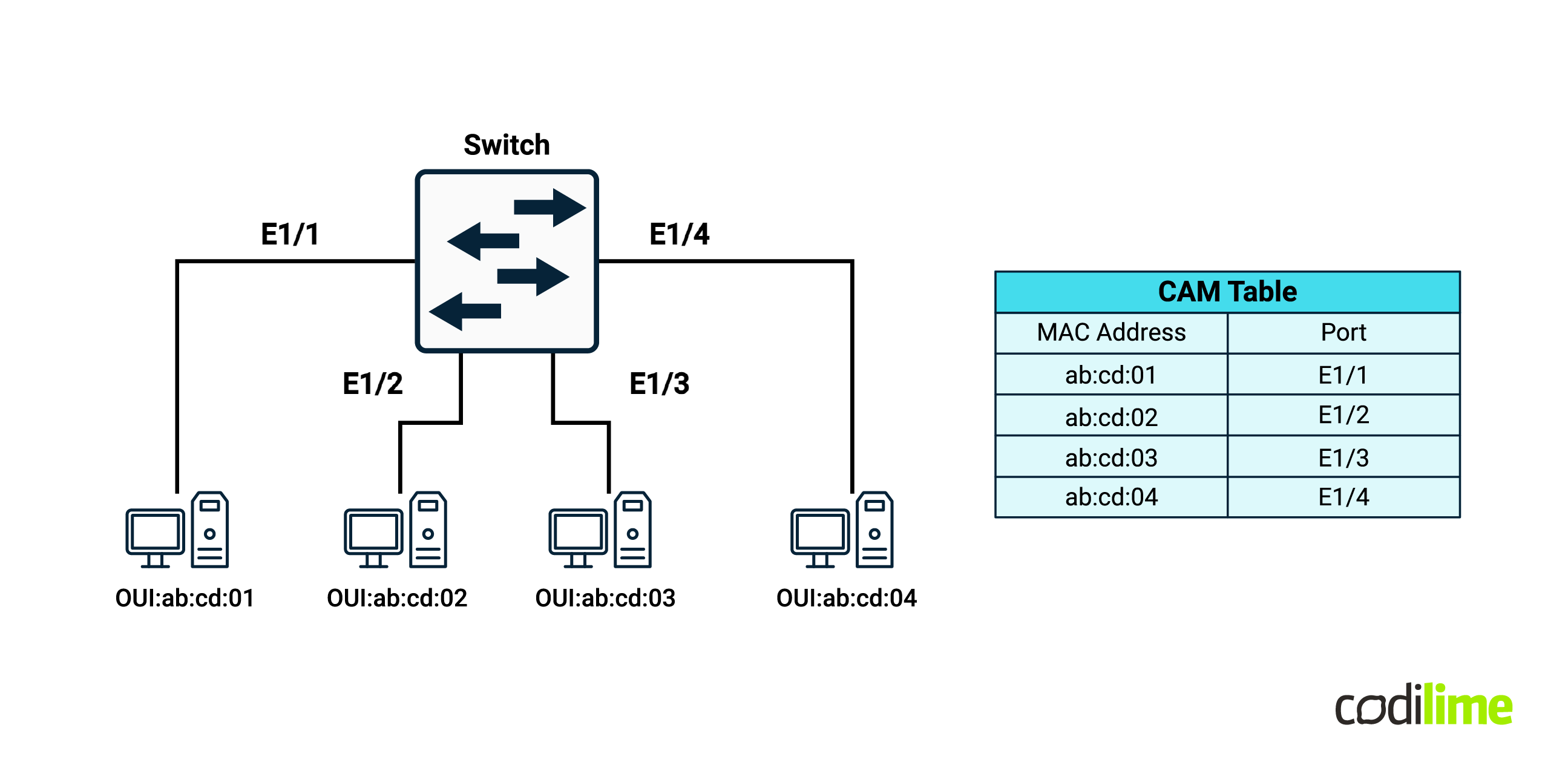
Above those numbers and legacy data centers start to struggle. And that’s mainly because of the MAC address propagation around the entire data center. In legacy layer 2 networking, if a switch has a VLAN configured locally, it’s going to automatically learn all of the MAC addresses within that broadcast domain and store them in the local CAM (content addressable memory) table. CAM is expensive - the bigger the number of MAC addresses, the more resources are required and the more costs go up.
Apart from this, some STP events within the network can flush the CAM table altogether and that will trigger a complete re-learning of the entire set of information - a process which can be very resource consuming.
Looking at BGP EVPN IP Fabrics on the other hand, MAC learning is done at the control plane level - the propagation of MAC-IP NLRI is handled by BGP - by the EVPN address family to be exact. BGP itself uses RAM (random access memory) which is considerably cheaper than its CAM counterpart.
Another optimization is that MAC information propagated by BGP is filtered by the local switch in such a way that only the required MAC addresses are downloaded in the local switch CAM table (yes, CAM tables are still used in IP Fabric devices as well for local MAC switching). By ‘required MAC addresses’ I mean the MAC addresses that a host on the local switch wants to communicate with.
The fact that IP Fabric uses layer 3 protocols at its core allows for much higher horizontal scaling. For layer 2 topologies - you can only scale as much as your STP domain allows you to - which is limited. Compared to that, the layer 3 protocols used as the building blocks for IP Fabric (OSPF/IS-IS as underlay routing, BGP as overlay and PIM for BUM traffic handling) can scale a lot better.
Convergence time
Convergence time in traditional data center networks is highly dependant on a few factors:
-
What is failing:
- An LACP bond member will not affect much,
- A complete TOR switch without MC-LAG or VPC or similar mechanism will have an impact.
-
Presence of STP “tricking”, such as link aggregation and MC-LAG/VPC:
- Such technologies allow a bypass of STP reconvergence by tricking the STP into thinking that the link is not affected and there should be no TCN (topology change notification) packet to be sent out or recalculation to be done.
-
STP implementation:
- MSTP with proper implementation or at least RSTP are mandatory and quite common nowadays for layer 2 topologies.
Long story short - the convergence time in layer 2 topologies is mainly dictated by STP! Other mechanisms such as link bundling and MC-LAG/VPC are also common and a requirement for current layer 2 architectures.
What about spine-leaf topology? Well, it depends where we’re looking:
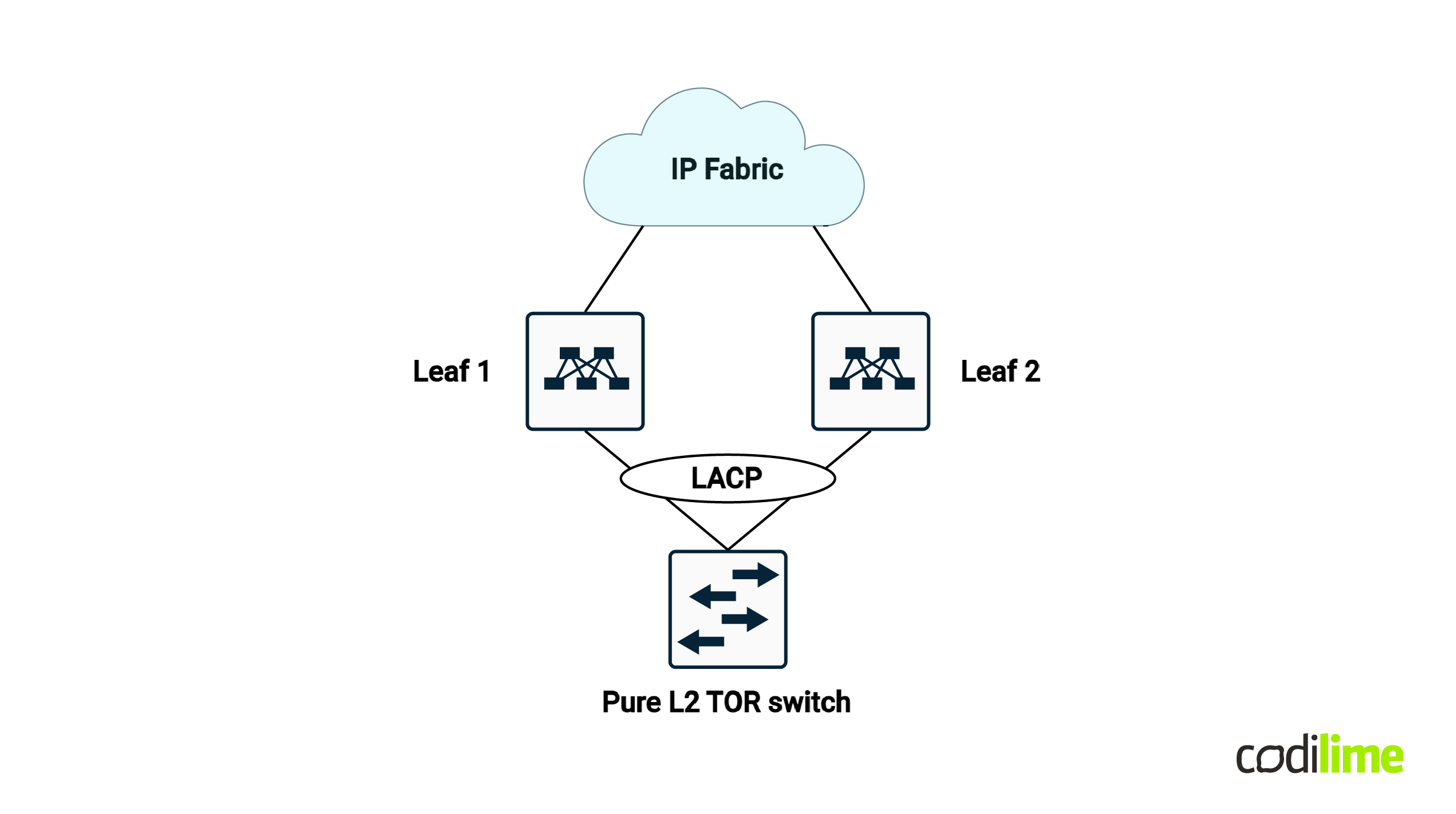
- At the leaf access layer - some implementations still run STP as you may have a layer 2-only switch dual homed connected to some leafs - so at that point there is not much we can do to enhance the convergence times - from the leaf downward to the layer 2 switch I mean, as you still might run into STP and/or link bundling.
- At the leaf-spine layer - this layer is a whole different story - everything works based on layer 3 protocols, so you can first of all tune those times for better performance. But that’s not the main advantage. The main advantage is the use of the BFD (Bidirectional Forwarding Detection) protocol that can bring your convergence time down to under100 msec
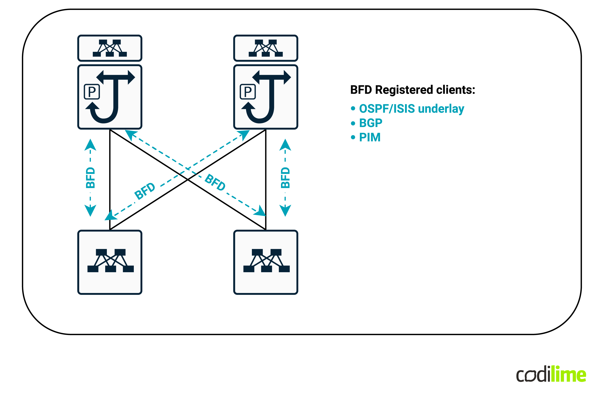
Once you deploy BFD between each leaf and spine link, you can register that BFD with all of your layer 3 protocols - BGP, OSPF/ISIS and even PIM. The result? Any link failure will instantly be detected and those protocols will have their adjacencies torn down in a fast programmable way - thus reducing convergence to a minimum.
- Another great advantage for IP Fabric designs is that you can completely isolate a specific leaf or spine from the rest of the Fabric in order to complete some operational tasks on it (like upgrades, hardware replacement, etc.) without impacting the traffic. Since IP Fabric uses BGP and OSPF/IS-IS (or BGP instead of OSPF/ISIS in IGP-free scenarios), you can simply either manipulate BGP to go around the leaf or you can use IS-IS overload-bit/OSPF max-metric LSA features to achieve the same result and take the leaf out of the forwarding path for the duration of the scheduled work.
Multitenancy
There is one key difference regarding multitenancy support between the architectures we are comparing - BGP EVPN VXLAN IP Fabric is able to also offer layer 3 tenancy while a traditional data center is purely based on layer 2 and can offer only VLAN segmentation.
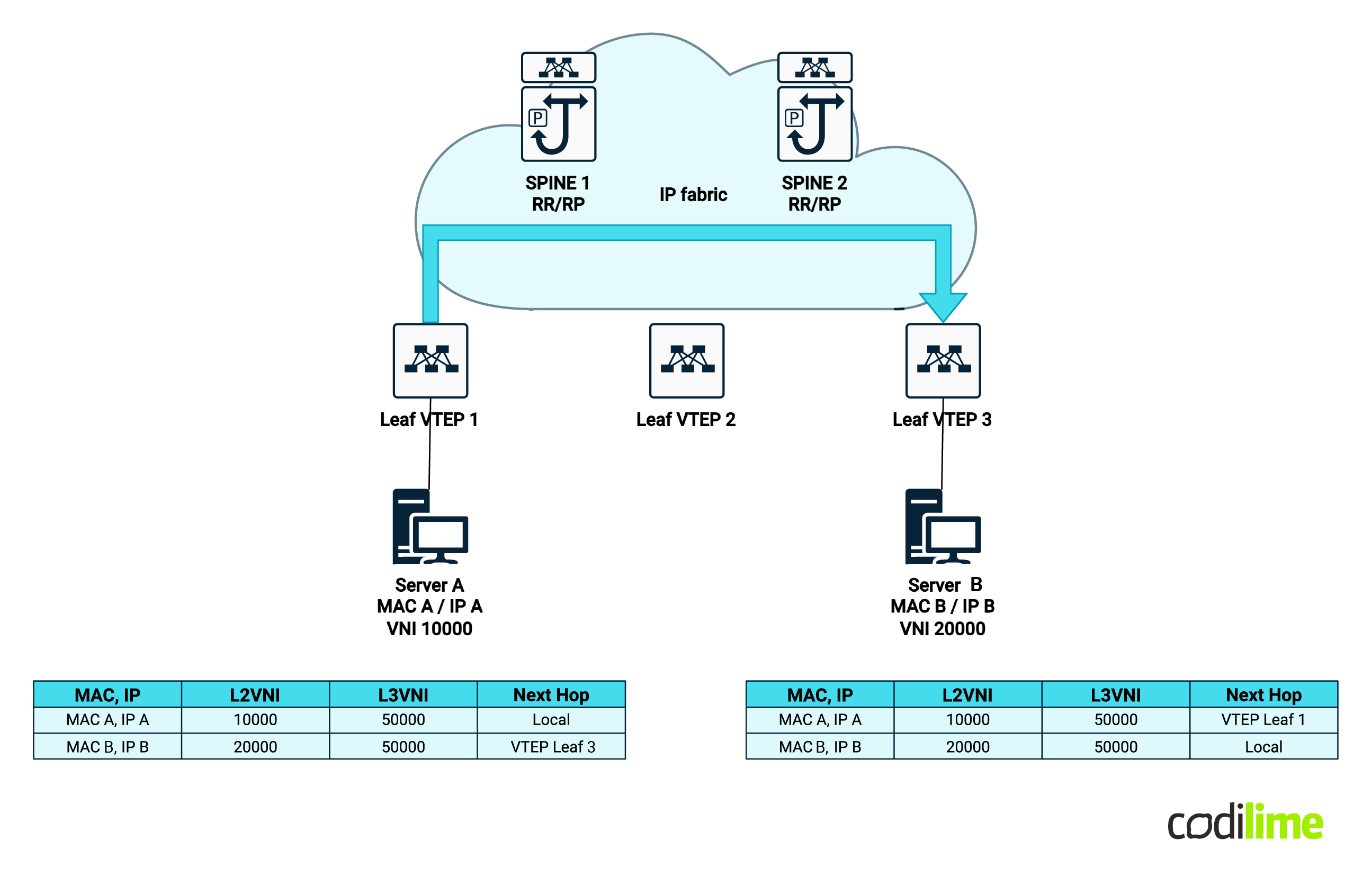
Layer 3 multitenancy works identically to MPLS layer 3 VPNs - which is by building and propagating dedicated routing table information for a given tenant, thus forming a new VPNv4/v6 unique prefix and controlling propagation by using their configured extended community route targets.
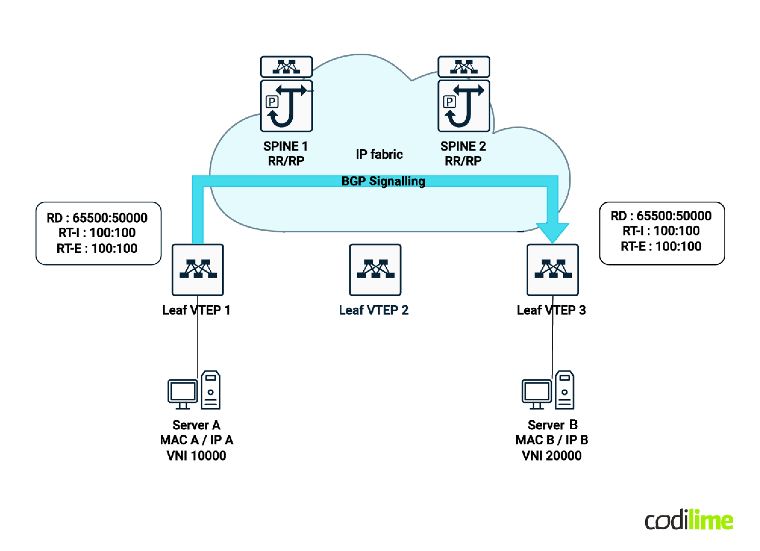
* Note: the BGP sessions are between spines and leafs - the diagram represents the BGP route NLRI propagation from one VTEP to another but this is done via the spines which have the route reflector function within the BGP EVPN VXLAN Fabric.
The spine-leaf design offers a clear advantage here as layer 3 multitenancy is a must nowadays and you don’t have to bring additional routers to handle that - they can be handled within the Fabric itself.
ECMP routing
Another interesting topic to consider when comparing the two technologies is ECMP (equal-cost multi-path) routing.
For legacy data centers, there is no true distinct link multi-pathing as STP will automatically block independently redundant ports between two switches. By independently redundant ports I am referring to ports that are not part of a link bond. If you want to achieve redundancy and resiliency, you can make use of link bonds but usually that is not the desired multi-pathing scenario.
Why not? Because you are relying on the bonds’ hashing algorithms which most of the time are not optimal - in many scenarios they do not take into account layer 4 header information (source/destination TCP/UDP ports). This leads to quick polarization (overutilization) of a single link of the X available in that specific bond.
For BGP EVPN VXLAN IP Fabric, inner packet header information is used for hashing the traffic across redundant links, usually using the following information:
- Source IP
- Destination IP
- Source port
- Destination port
- Protocol number
Using this information, and due to the fact that there is no additional protocol to prune any of the links, true ECMP can be achieved.
Configuration complexity
IP Fabric has won a few rounds by now, but it surely won’t win this one. The biggest challenge when switching to such a technology is the complexity. Let’s take a brief look at what a simple VLAN layer 2 service configuration looks like on a traditional layer 2-only switch (left side) versus a leaf (right side), taking Cisco Nexus NX-OS as an example (don’t worry - the complexity is there across all vendors with IP Fabric configurations):
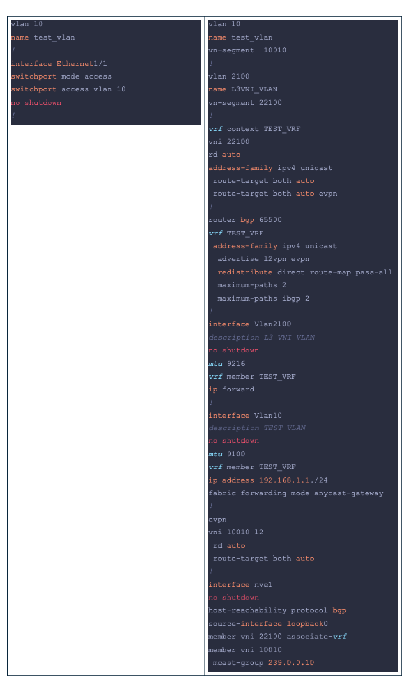
The difference is obvious and the prerequisites to be able to understand everything properly is just much higher for spine-leaf technologies. If we compare the requirements knowledge-wise, we get:
-
For layer 2:
- STP,
- Link bonding,
- VLANs.
-
For IP Fabric - all of the above plus:
- BGP (IPv4 and L2VPN EVPN),
- VRFs,
- VXLAN,
- Multicast,
- BFD.
And it’s not just a numbers comparison (three items vs. five items), you can usually read an article about VLANs and you be able to understand the topic but you can read three or four books about BGP and there’s a good chance you still have not covered all of the use cases for it.
This leads us to one important note: if your topology is simple and very small (e.g. just one or two switches), stick to layer 2! It’ll do its job!
Fortunately, there is something that can get us out of the configuration mud that comes with BGP EVPN VXLAN: automation!
Programmability and automation
Automation is useful everywhere and can be implemented for both legacy data center technologies and for spine-leaf use cases as well and it surely brings advantages to both. However, it makes a lot more sense to use it for IP Fabric deployments due to the sheer amount of configuration and risk of error (there is a great amount of linking VNI numbers between configuration items across multiple devices which can very easily be mistyped). For legacy data centers, automation can be of help dealing with VLAN management (adding, removing, swapping, etc.) which is of much less complexity compared to the IP Fabric operational overhead.
There is a huge spectrum of automation tools and solutions out there to choose from that can meet your needs (for more information on which network automation tools you can choose - please visit our previous article about network automation tools).
There is one small advantage regarding automation for IP Fabric architectures - the devices used for building such topologies are by default newer than the ones used in legacy data centers. This means that they are more programmable and a lot of them offer some type of API system (REST, XML, NETCONF, etc.) which makes configuring, reading and parsing devices much faster than handling SSH sessions and parsing their unformatted outputs.
Keep in mind that any type of automation is much better than no automation at all - so this point would be a tie between the two architectures; with a slight advantage to IP Fabric that comes natively due to device evolution rather than the development of a specific feature.
Hardware costs
The more features, the more things you can do with them, and the higher the costs. It would be inherently more costly to implement a spine-leaf data center compared to a legacy data center.
The advantage in this regard is that newer devices support some type of IP Fabric implementation by default and don’t need a specific hardware component for it while also shipping backwards compatibility to support layer 2 as well.
Conclusion
In conclusion, if you are implementing a new infrastructure that requires more than one or two switches with at least a two-layered design, spine-leaf architecture is the way to go; even if we are talking about enterprise networks or large service providers.
Traditional data centers will still exist for at least another 5 to 10 years, especially due to the time and effort required to transition to modern architectures like IP Fabric. I do expect that in time spine-leaf architecture will become the de facto solution for any medium to large-scale data center design!


