Networking devices are complex and characterizing their performance is not easy. One must not judge performance based only on the number and type of ports. On the other hand, the performance figures that can be found in marketing materials may not be conclusive. Therefore, some while ago, the effort was made to create a unified benchmarking methodology to produce reliable, repeatable and comparable results.
In this short article we’ll describe the basic performance metrics of networking devices and the methodology used to measure them. While there is no single standard for testing network devices we’ll focus on one of the first documents and probably the most recognizable one covering the topic, namely RFC 2544 . It is noteworthy that this RFC is not an official standard, it is categorized as informational.
Network testing terminology
Before describing the testing it’s important to establish some common terminology. The most important terms are listed below along with short descriptions. Some of them are defined and described in more detail in RFC 1242 .
- DUT (device under test) - the device being tested. Sometimes, SUT (system under test) is used instead.
- Throughput - The maximum rate at which a device is able to forward frames without dropping any of them. The term is quite often used as a synonym for traffic rate without considering the no-loss requirement. In such cases throughput, as defined in the RFC, is called ‘zero-loss throughput’. Throughput consists of two variables: PPS (packets per second) and packet size. PPS multiplied by size gives us BPS (bits per second).
- Frame loss rate - The percentage of frames that were sent to the DUT but were not forwarded due to lack of resources on the DUT.
- IFG (interframe gap) - Sometimes named IPG (interpacket gap) is the gap between two subsequent frames. It is the time interval between sending the last bit of the first frame and first bit of preamble of the second frame. Each media type requires a minimum IFG necessary for its proper operation.
- Back-to-back - fixed-length frames sent to the device at a rate such that the IFG between frames is the minimum IFG allowed for a given medium.
- Latency - In general this is how long it takes for the device to process a packet. The exact definition depends on device type. For “store-and-forward” devices it is defined as the time interval between the last bit of a packet reaching the input port to the first bit of a frame leaving the output port. The other type of device is “cut-through” which starts transmitting the frame before the last bit of the frame is received. For this kind of device latency is defined as the interval between receiving the first bit on input port and transmitting the first bit on output port.
Testing methodology
Although not explicitly stated in RFC 2544 , the tests defined there are not intended to be used in production networks. Furthermore, use of RFC 2544
tests in production networks is considered harmful as described in RFC 6815
. The rationale for not using these tests in production are twofold.
Firstly, tests may have a negative impact on the production network. Some tests, for instance throughput tests, try to measure maximum load. In the presence of additional production traffic such tests can easily overload the device causing it to drop production traffic or making the device unstable or even crash in the worst case. Secondly, additional production traffic will interfere with test traffic causing results to be inaccurate and inconsistent.
Therefore it is highly recommended to run these tests in dedicated isolated test environments.If such a scenario is impossible then the following minimum steps should be taken:
- Run performance tests during a maintenance window, AND
- Use the 192.18.0.0 - 192.19.255.255 address space which is reserved for testing purposes and should not overlap with network addressing.
This way potential interference will be kept to a minimum.
RFC 2544 defines the number of tests. Each definition describes the procedure for how to perform a given test as well as the test results format. Tests are expected to be device agnostic and don’t use any device-specific functionalities. Similarly, tests don’t assume the DUT operates on a particular ISO layer or runs a particular protocol (for instance an IP version).
Test definitions include numerous requirements but not all of them are mandatory. They are grouped as mandatory/recommended/optional following the RFC MUST/SHOULD/MAY convention as described in RFC 2119 .
The most noteworthy ones are:
- Tests should be run multiple times using frame sizes ranging from the minimum to maximum allowed by the tested medium or by device.
- Bidirectional traffic should be used for testing.
- Stateless UDP traffic must be used.
- If the DUT is modular, ports from different modules should be used for testing.
- Tests should be also performed with control traffic (e.g. SNMP queries or routing protocol updates) reaching the DUT during the test. The goal of such a test is to verify whether control plane traffic impacts DUT performance.
- If applicable, tests should be performed with traffic filters configured on the DUT to verify the filters’ impact on DUT performance. Tests should be performed at least twice with filters of different sizes.
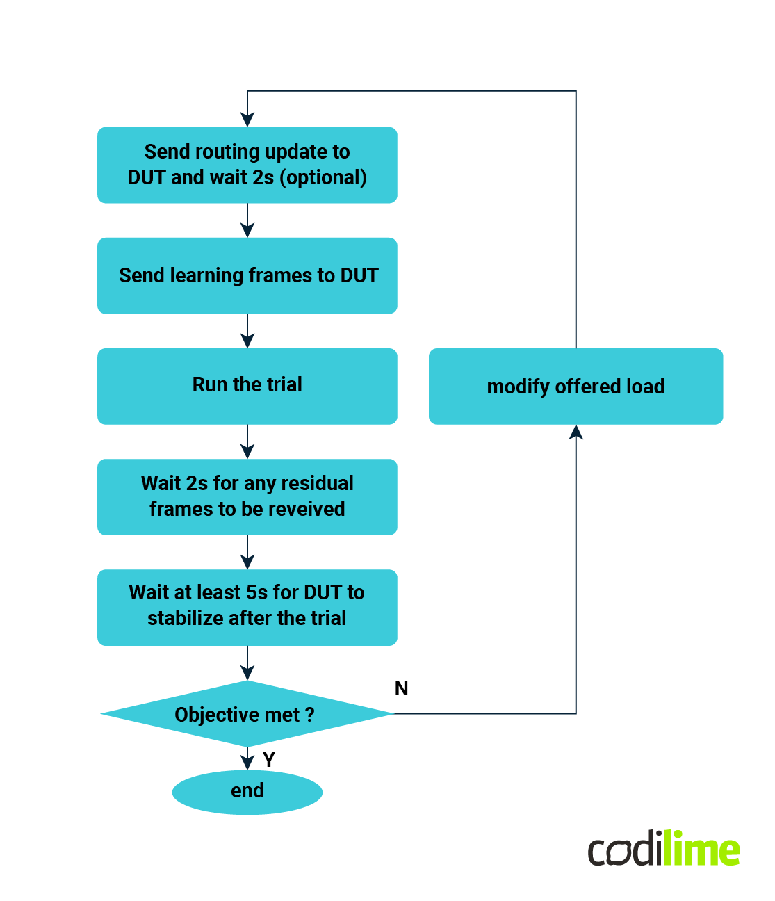
The test procedure is common for most of the tests. A test usually consists of multiple trials run with different parameters, as shown below. The test ends when the test objectives are met (e.g. zero loss throughput is found, quite often with a given tolerance) or can be terminated after exceeding a given number of iterations.

The iterative nature of tests makes them a perfect candidate for automation and indeed many network testers offer the possibility of performing these tests automatically.
Throughput test
This test’s objective is to determine the DUT’s throughput (i.e. zero-loss forwarding rate).
The test procedure is to send frames of a given size at a specific rate through the DUT and count the number of dropped frames. If frames are dropped, the trial is repeated with a decreased frame rate. The RFC doesn’t specify how the frame rate should be increased/decreased. An intermediate result is a frame rate at which no frames get dropped. Then the process is repeated for different frame sizes.
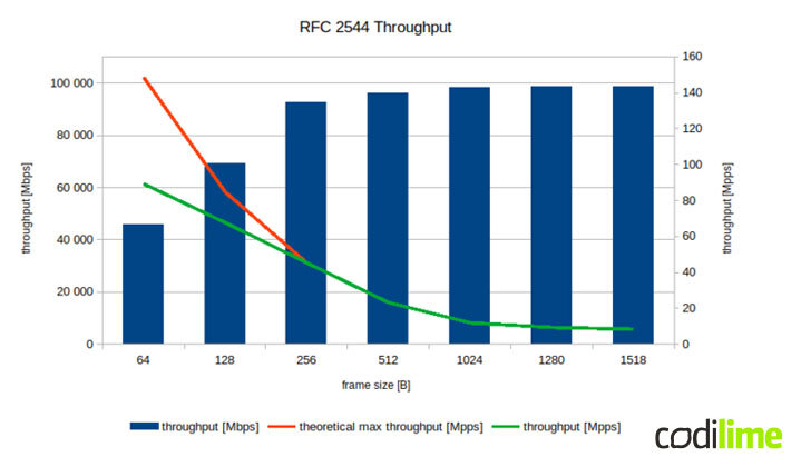
The recommended result format is a graph showing the frame rate for different frame sizes. The graph should also include the maximum theoretical frame rate for the media used in the test. If a single value result is desirable, the maximum frame rate for the smallest frame size for the given media must be used. Additionally, the theoretical maximum frame rate for that frame size and the protocol used in the test must be specified. An example of a results graph is shown below.

Latency test
The objective of the test is to determine the latency introduced by the DUT.
The test procedure is to send frames of a given size at the maximum rate measured for a given frame size in the throughput test through the DUT and measure the latency.
The recommended result format is a table showing the latencies for each frame size. The results must also specify how the latency was measured (store-and-forward vs. cut-through). An additional requirement is that the test must be repeated at least 20 times and the average latency must be reported. It’s also useful to report the minimal, maximal and latency variation (jitter) however the RFC2544 doesn’t require this.
Frame loss rate
The objective of the test is to determine the frame loss rate under overload conditions. The test is run for different offered load rates and frame sizes.
The test procedure is to send frames through the DUT at a specified rate and count the percentage of frames dropped. The test starts with a frame rate of 100% of the theoretical maximum frame rate which most likely exceeds the DUT’s forwarding capability. The offered load is decreased by at most 10% (finer steps are allowed and encouraged) in subsequent trials until no frames are dropped in two successive trials.
The recommended result format is a graph showing the frame loss rate over the offered load. The results for different frame sizes may be represented by additional lines on the graph.
Back-to-back frames test
The objective of the test is to determine the DUT’s ability to process bursts of frames sent with the minimum allowed interframe gap.
The test procedure is to send a burst of frames through the DUT and verify whether all frames are forwarded. In subsequent trials, the number of frames in the burst is increased if no frames are dropped or decreased otherwise.
The recommended results format is a table showing the back-to-back value for all frame sizes. Some additional discussion on back-to-back tests, especially in virtualized environments, can be found in RFC 9004 .
System recovery test
The objective of the test is to determine how long it takes the DUT to recover from overload conditions.
The test procedure is to send 110% of the measured throughput (or maximum theoretical if smaller) to the DUT for at least 60 seconds, then decrease the offered load to 50% of the throughput and observe when the DUT stops dropping frames. The recovery time is the time between decreasing a load and when the last frame is dropped.
The recommended result format is a table showing the recovery time for different frame sizes.
Reset test
The objective of the test is to determine the DUT’s ability to recover from the reset condition.
The test procedure is to perform a DUT reset while offering a load at the throughput rate and measure how long it takes the DUT to start forwarding frames again. RFC 6201 provides more details on reset condition testing as well as defining additional tests such as routing processor or line card resets.
Further reading
Because RFC 2544 predates many protocols, additional documents have been released to describe the testing of particular protocols or use cases. The most notable among these are:
- RFC 5180
- IPv6 Benchmarking Methodology for Network Interconnect Devices,
- RFC 5695
- MPLS Forwarding Benchmarking Methodology for IP Flows,
- RFC 2285
- Terminology for LAN switching devices,
- RFC 2889
- LAN Switch Benchmarking Methodology,
- draft-dcn-bmwg-containerized-infra
- Considerations for Benchmarking Network Performance in Containerized Infrastructures,
- ETSI GS NFV-TS
- Specification of Networking Benchmarks and Measurement Methods for NFVI (and related docs).
Conclusion
A lot has changed in networking since RFC 2544 was released back in 1999. Huge progress has been made in the area of physical networking devices. New media types and networking protocols have been invented, and virtualized networking solutions have appeared on the networking scene.
Despite so many changes, the basic concepts described in RFC 2544 are still relevant and are worth knowing. The best illustration of this is that despite being over 20 years old RFC 2544 is still being referenced in documents related to network testing.


