


The proof of concept and our conclusions
In the previous part, we introduced both the higher and the lower level concepts necessary for understanding the use case scenario as well as a proposed solution, starting from its prerequisites through to the design and finally the implementation.
In this concluding article of the series, we want to eventually answer the initially-posed question: can we adapt a SONiC switch to be able to deliver a custom functionality? In our case, a load balancing feature for GTP-U.
The plan
In order to conduct this PoC we needed to:
-
Choose an appropriate technique, which is reliable and can be expected to give consistent results across all potential deployments. Its job is to be able to look into the payload of a UDP datagram, extract the TEID field and distribute (forward) these datagrams to the appropriate endpoints → user defined fields (UDF) based ACLs were chosen here.
-
Check what needed to be implemented and where:
- Modification of two SONiC modules: Orchagent and SyncD.
- The modification added the logic necessary for them to handle UDFs and UDF-based ACLs.
- The modified modules needed to be installed on the test SONiC switch, substituting the original.
-
Choose a hardware platform able to run the test scenario in order to conclude the PoC.

The execution
Choosing the hardware platform
As explained in part 2 of our series, ACL tables are not being effectively programmed into the SONiC virtual switch (ACLs are inserted into the SONiC’s internal database, but the data plane is not programmed to reflect that ACL configuration). In order to finalize and test our proof of concept, it was necessary to acquire a real piece of hardware capable of running SONiC.
When looking for a candidate, first we checked the list of SONiC-supported platforms ![]() . The next step was to check the specific version of SAI (Switch Abstraction Interface) a particular ASIC vendor supports in a specific chipset - and that turned out to be surprisingly hard to figure out. This was essential since our development depended on SAI support of specific features i.e. UDF and UDF-based ACLs (earlier versions of SAI did not yet define/support UDFs and UDF-based ACLs were added even later). Even particular SAI version support is not enough as ASIC vendors may implement a specific SAI version but with some exceptions (e.g. a feature does not support a particular parameter).
. The next step was to check the specific version of SAI (Switch Abstraction Interface) a particular ASIC vendor supports in a specific chipset - and that turned out to be surprisingly hard to figure out. This was essential since our development depended on SAI support of specific features i.e. UDF and UDF-based ACLs (earlier versions of SAI did not yet define/support UDFs and UDF-based ACLs were added even later). Even particular SAI version support is not enough as ASIC vendors may implement a specific SAI version but with some exceptions (e.g. a feature does not support a particular parameter).
In short, this is definitely an important factor you need to consider when choosing your hardware. There is no “one SAI fits all” principle here.
Considering those factors, we decided to employ the Mellanox/NVIDIA Spectrum SN2010 switch for our proof of concept. Mellanox/NVIDIA publishes its SAI implementation ![]() for Spectrum ASICs and it (at the time of writing this article) supports SAI version 1.10 (the latest, although with some limitations
for Spectrum ASICs and it (at the time of writing this article) supports SAI version 1.10 (the latest, although with some limitations ![]() ).
).
Building for the chosen hardware platform
This is where the SONiC container-based architecture shines. Even though we implemented a new SONiC functionality, there was no need to build the whole system from scratch.
SONiC images (and other build artifacts) for various platforms are publicly available in the SONiC Image Azure Pipelines ![]() . Following the SONiC User Manual
. Following the SONiC User Manual ![]() , we downloaded a regular SONiC image for the Mellanox platform and installed it on our switch.
, we downloaded a regular SONiC image for the Mellanox platform and installed it on our switch.
Having a regular SONiC system in place, we needed to update the two services (docker images) that contained the changes we prepared in the development phase:
- Orchestration Agent, aka. orchagent
- Synchronization Daemon, aka. syncd
The SONiC build system requires specifying the target ASIC platform. We used a VS (Virtual Switch) during the development phase, but then we needed images for the physical Mellanox switch. The docker images for Mellanox were built without problems, at the first attempt.
Then we just uploaded the updated images to the switch’s Docker daemon, removed the old images, rebooted the switch, and voilà. The updated services were up and responsive.
Based on that experience, we can agree that SONiC keeps its promise of being modular in terms of deployment.
What and how did we test - the lab
To test our implementation on the data plane level, i.e. to check if sample GTP-U packets are load balanced according to the configured rules, we built a simple setup emulating our use case scenario, consisting of:
- Mellanox/NVIDIA Spectrum SN2010 switch with SONiC NOS (upstream build with changed swss and syncd components).
- A BMS (Bare Metal Server) running Linux (Ubuntu 20.04), connected to the switch by three links.
A base configuration (allowing to forward packets from a traffic generator to two traffic endpoints) for the SONiC switch was simple: IP addresses assigned to interfaces connected to the server and a routing entry for the target IP address. Next, we added the configuration for UDFs (UDF Match, UDF Group and UDF) as well as for ACLs (ACL Table and ACL rules). As a result, the switch was expected to forward GTP-U packets to traffic endpoint No.1 if the TEID field’s last bit was equal to 0 or to traffic endpoint No.2 if the TEID field's last bit was equal to 1. This is depicted in the figure below:
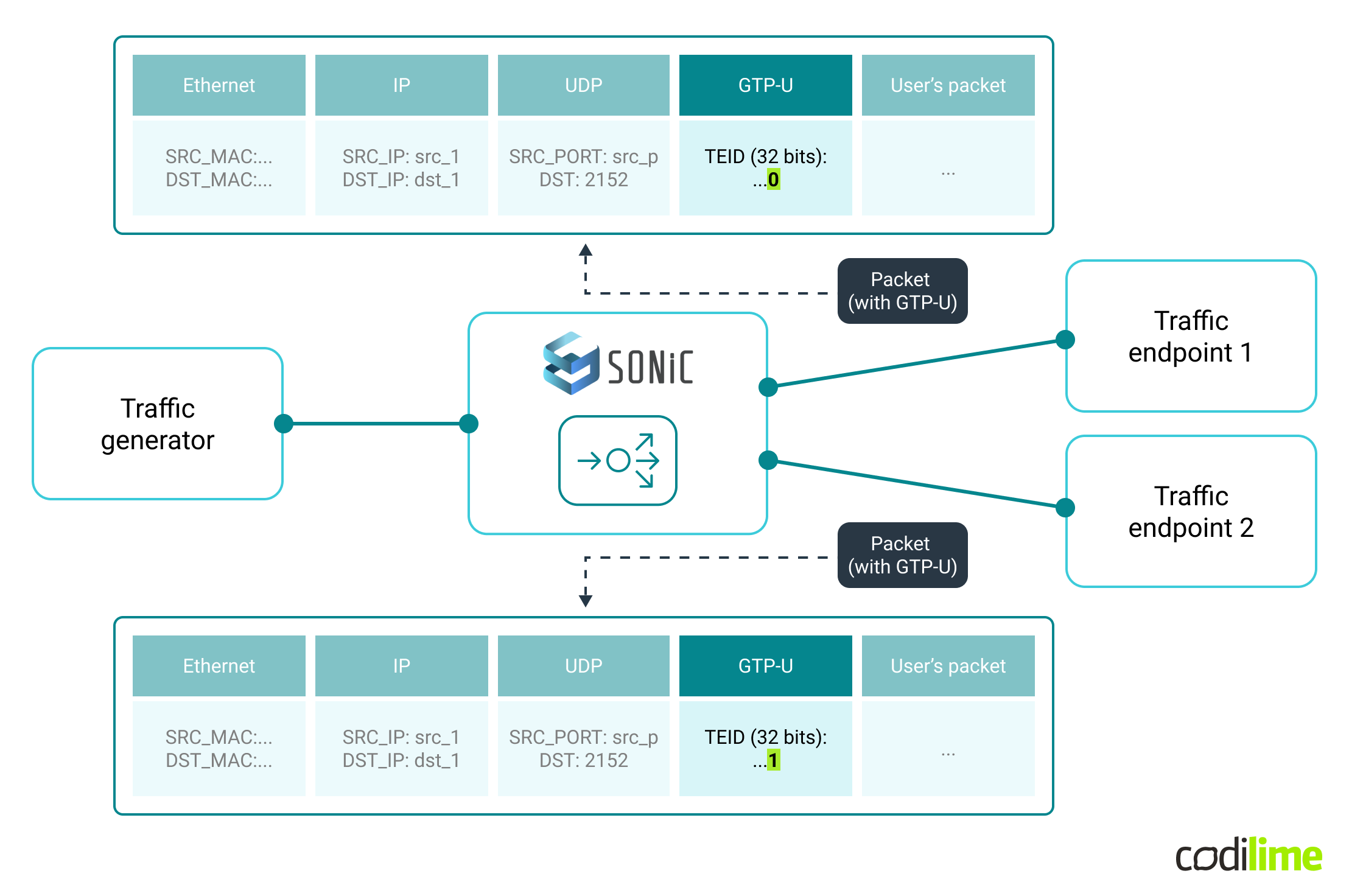
Sample GTP-U packets have the same source and destination IPs, and the same UDP ports (as is often the case in real-life implementations) but they differ by the GTP-U TEID field values and based on that are forwarded to the desired endpoint.
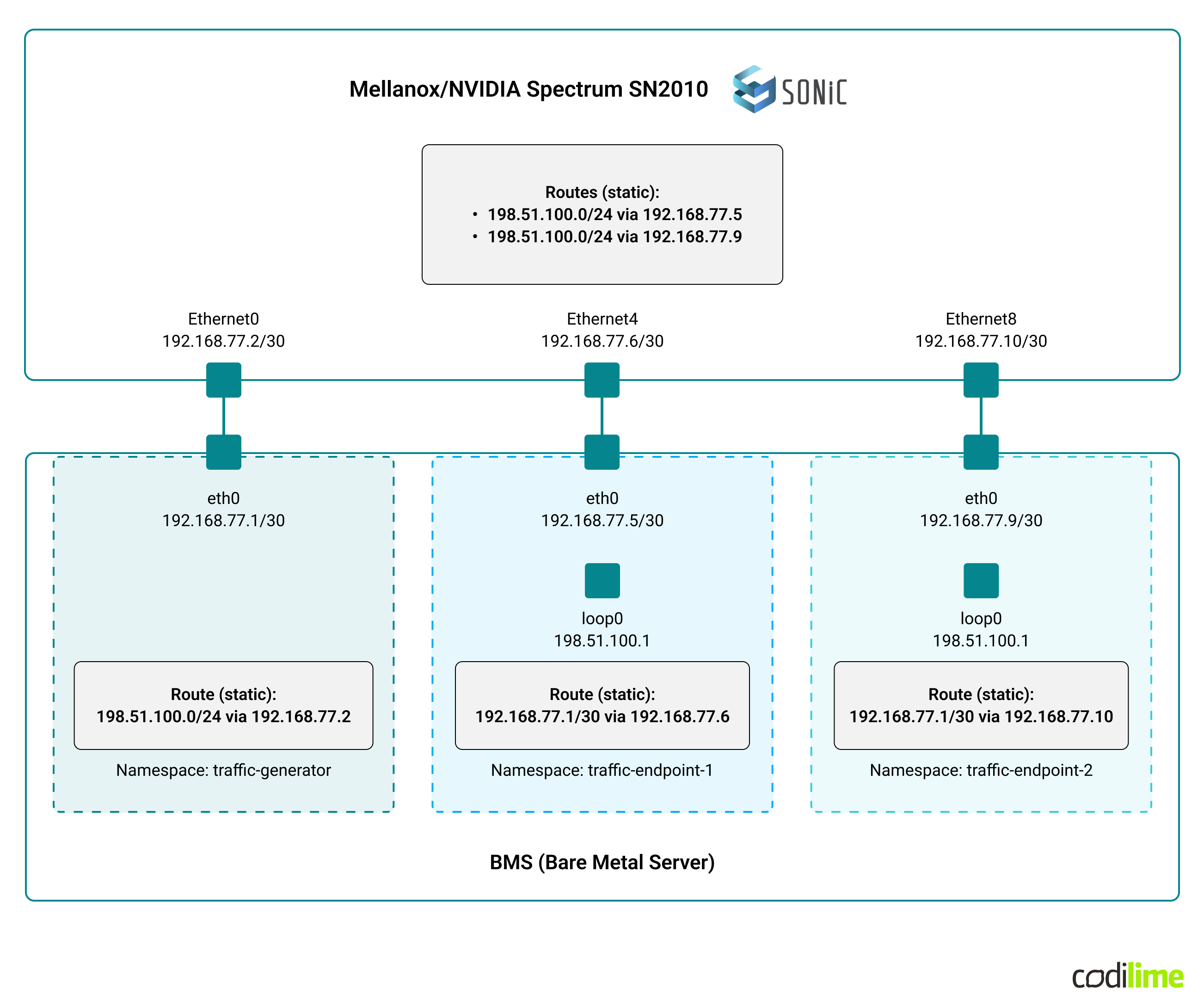
BMS with Ubuntu was used to simulate GTP-U traffic source (e.g. 5G gNB aka gNodeB), depicted as traffic generator, and endpoints (e.g. 5G UPFs - User Plane Function). Linux Network Namespaces were employed to separate the traffic generator and the endpoints with relevant physical network interfaces being moved to those namespaces (so that IP addresses assigned in namespaces were not directly reachable from other namespaces nor from the host OS).
The connectivity between the switch and the BMS as well as layer 3 configuration (IP addressing and routing entries) is shown in the diagram below:
The Python Scapy ![]() library was used to prepare a simple GTP-U packet generator to be used on the source side as well as to capture (sniff) and count the incoming packets in the endpoints’ namespaces.
library was used to prepare a simple GTP-U packet generator to be used on the source side as well as to capture (sniff) and count the incoming packets in the endpoints’ namespaces.
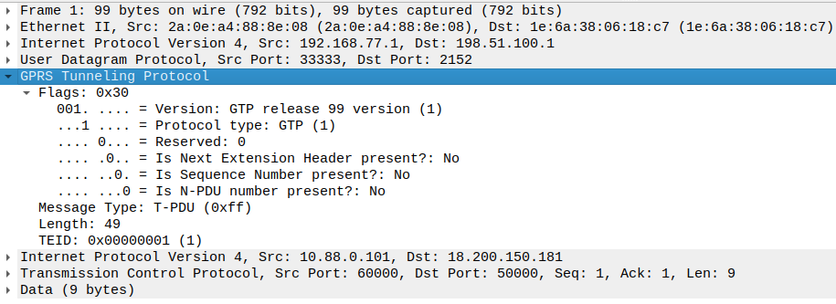
A sample GTP-U packet, generated using the Python Scapy library, captured at a traffic endpoint’s interface and displayed by Wireshark looks like this:
To create, within the source namespace, GTP-U packets with TEID=0 - 19 (0, 1, 2, …,19) and to send them through the SONiC switch to endpoints’ namespaces, the following commands were used:
$ sudo ip netns exec source scapy -H
Welcome to Scapy (2.4.5) using IPython 7.13.0
>>>
>>> from scapy.contrib.gtp import *
>>> pkts=IP(src="192.168.77.1",dst="198.51.100.1")/UDP(sport=33333,dport=2152)/GTP_U_Header(teid=[(0,19)],gtp_type=0xff)/IP(src="10.88.0.101",dst="18.200.150.181")/TCP(dport=50000,sport=60000,flags="PA",seq=12,ack=8)/"Test data"
>>> send(pkts)
....................
Sent 20 packets.
>>>
One can see that a set of 20 IP packets was defined (with specific source and destination IP addresses), carrying UDP (with the destination port of 2152, which is assigned to GTP-U) and GTP-U header. The TEID field contained a list of values (from 0 to 19) and the GTP-U payload (emulating end user traffic) was set to sample IP addresses with TCP ports.
On the endpoints’ side, a simple Python script (Scapy based), which captured and filtered traffic (only GTP-U was of interest), was used. Information about the intercepted GTP-U packets was displayed - the total number and TEID from received GTP-U packets.
Traffic endpoint 1:
$ sudo ip netns exec endpoint-1 python listener-endpoint-1.py

Packet #1: 192.168.77.1:33333 -> 198.51.100.1:2152 TEID: 0
Packet #2: 192.168.77.1:33333 -> 198.51.100.1:2152 TEID: 2
Packet #3: 192.168.77.1:33333 -> 198.51.100.1:2152 TEID: 4
Packet #4: 192.168.77.1:33333 -> 198.51.100.1:2152 TEID: 6
Packet #5: 192.168.77.1:33333 -> 198.51.100.1:2152 TEID: 8
Packet #6: 192.168.77.1:33333 -> 198.51.100.1:2152 TEID: 10
Packet #7: 192.168.77.1:33333 -> 198.51.100.1:2152 TEID: 12
Packet #8: 192.168.77.1:33333 -> 198.51.100.1:2152 TEID: 14
Packet #9: 192.168.77.1:33333 -> 198.51.100.1:2152 TEID: 16
Packet #10: 192.168.77.1:33333 -> 198.51.100.1:2152 TEID: 18
Traffic endpoint 2:
$ sudo ip netns exec endpoint-2 python listener-endpoint-2.py

Packet #1: 192.168.77.1:33333 -> 198.51.100.1:2152 TEID: 1
Packet #2: 192.168.77.1:33333 -> 198.51.100.1:2152 TEID: 3
Packet #3: 192.168.77.1:33333 -> 198.51.100.1:2152 TEID: 5
Packet #4: 192.168.77.1:33333 -> 198.51.100.1:2152 TEID: 7
Packet #5: 192.168.77.1:33333 -> 198.51.100.1:2152 TEID: 9
Packet #6: 192.168.77.1:33333 -> 198.51.100.1:2152 TEID: 11
Packet #7: 192.168.77.1:33333 -> 198.51.100.1:2152 TEID: 13
Packet #8: 192.168.77.1:33333 -> 198.51.100.1:2152 TEID: 15
Packet #9: 192.168.77.1:33333 -> 198.51.100.1:2152 TEID: 17
Packet #10: 192.168.77.1:33333 -> 198.51.100.1:2152 TEID: 19
Packets were forwarded to traffic endpoint No.1 or traffic endpoint No.2 depending on TEID field value - custom load balancing implemented on the SONiC switch worked as expected. The test was repeated several times with different combinations of TEID values and additionally other fields of IP packet were changed (e.g. UDP source port, GTP-U payload) - the end result was the same.
SAI implementation - real-life check
We’ve already mentioned the hardware platform selection challenges related to SAI versions. Having the SONiC switch and testing the implementation for our use case allowed us to verify support for specific options and parameters which we initially planned to use. Checking the release notes ![]() (of Mellanox/NVIDIA SAI) helped to figure out the real status of the SAI API implementation. Below we present our observed limitations (related to the use case we built).
(of Mellanox/NVIDIA SAI) helped to figure out the real status of the SAI API implementation. Below we present our observed limitations (related to the use case we built).
Relevant (to our use-case) limitation based on release notes:
-
a) Only L2 matches which can be ARP/IPv4/IPv6 ethertype or empty are supported
b) An empty match is only supported for SAI_UDF_BASE_L2
c) Non-empty matches (ARP/IPv4/IPv6) are only supported for SAI_UDF_BASE_L3
This means:
a) Only L2 (EtherType field from Ethernet header) matches are supported. SAI specification also defines L3 (Protocol field from IP header) matches but they were not implemented in the Mellanox SAI - below are the logs from SONiC when the L3 match was specified:
sonic ERR syncd#SDK: [SAI_UDF.ERR] mlnx_sai_udf.c[1829]- mlnx_sai_create_udf_match: SAI_UDF_MATCH_ATTR_L3_TYPE is not supported
b) If there is no EtherType specified in UDF Match (empty match), layer 2 is used as a base (UDF offset base from the start of L2 header)
c) If the EtherType is specified (supported types: ARP/IPv4/IPv6) layer 3 is used as a based (UDF offset base from the start of L3 header)
Initially, we also wanted to filter packets based on IP protocol type/number (to match only UDP packets) but it turned out not to be possible (this was eventually not an issue as filtration was done by ACLs).
- UDF Base
 :
:
a) If L2 – Support only one UDF in the UDF group
b) If L3 – Support up to three UDFs in the UDF group. UDF matches should be unique within the UDF group
Where:
a) L2 - SAI_UDF_BASE_L2 ![]() (UDF offset base from the start of L2 header)
(UDF offset base from the start of L2 header)
b) L3 - SAI_UDF_BASE_L3 ![]() (UDF offset base from the start of L3 header)
(UDF offset base from the start of L3 header)
Note: “SAI_UDF_BASE_L2” and “SAI_UDF_BASE_L3” are supported, but “SAI_UDF_BASE_L4” is not. As a consequence, we had to count the UDF OFFSET from the beginning of the layer 3 header and not layer 4 (as initially planned).
This means that the ACL Table can be bound to the ingress stage, but not the egress stage (ACL stage defines at which point in the packet processing pipeline ACL rules are applied. Visual representation of the pipeline with different ACL stages is also shown in our first article about SONiC - link). However when checking the configuration using VLANs (a single link between the BMS and switch with three VLANs to separate traffic), it turned out that ACL Table could not bind to the VLAN interface (even though it was set to ingress stage):
sonic ERR syncd#SDK: [SAI_ACL.ERR] mlnx_sai_acl.c[21006]- mlnx_acl_table_bind_point_list_fits_group: ACL Group's bind point type (SAI_ACL_BIND_POINT_TYPE_VLAN) is not supported for ACL Table (0)
In our use case, the switch port bind point was used instead for ACL Table (“SAI_ACL_BIND_POINT_TYPE_PORT ![]() ”) and additional filtering criteria in ACL rules were added (matching the given VLAN ID).
”) and additional filtering criteria in ACL rules were added (matching the given VLAN ID).
Additionally, we observed surprising behavior related to the UDF value set in the ACL rule (to compare with that extracted by UDF objects). This value is internally kept as a list of 1-byte fields. It turned out that if the UDF length is equal to 2 bytes (meaning a list consisting of two values, each of length of 1 byte), each part of the value has to have different values:
sonic ERR syncd#SDK: [SAI_UTILS.ERR] mlnx_sai_utils.c[842]- sai_attribute_value_list_is_unique: Attribute SAI_ACL_ENTRY_ATTR_USER_DEFINED_FIELD_GROUP_MIN contains equal elements at indexes 0 and 1
We have only checked ACL rules with UDF lengths of 1 and 2 - behaviors for longer UDF fields were not verified.
To sum up the POC
The proof of concept demonstrated that once we have migrated the modified modules to the physical switch, a few vendor-specific problems arose in the process. To address these, we needed to apply two types of accommodations:
- invasive, i.e. the ones which forced us to waive some less crucial parts of the solution (specifically, the step of making sure that only packets containing UDP are processed),
- non-invasive, i.e. the ones for which we needed to develop a workaround, but the functionality was retained (e.g. the base for counting the offset for UDF).
After adjusting to the limitations we could finally run our solution using an appropriate lab setup to verify that the test traffic was being balanced according to our expectations. Eventually we managed to implement a working solution using the adapted SONiC modules in a physical switch.
All of that got us a chance to get our hands on custom SONiC feature development andlearn how to do it, what the limitations are and how to circumvent them, plus what to leverage and what to avoid.
What may come next?
Since the PoC has proven the feasibility of the concept, the work may be taken further, leading to releasing a fully-fledged, production-ready piece of software.
So what would we do next, to make that happen?
- Performance tests - because one of the key benefits expected from a hardware solution designed to process high loads of traffic is its performance (scalability and throughput).
- Redundancy - our implementation does load balancing with a static (configured) number of endpoints, but a real deployment would be required to handle situations when one or more endpoints fail.
- Developing YANG models for UDF and updating them for ACL (to include UDF) - because SONiC uses YANG models to expose its features to the user (by means of a CLI, gNMI or REST API).
- Endpoint capacity (i.e. number of served endpoints) - because a production deployment will not be that simple. It is important to provide support for a higher number of served endpoints (any reasonable number, also not being a power of 2).
- Universal UDF implementation - our UDF implementation was simplified and tailored to support only our use case. A generic SONiC UDF implementation would require a more flexible UDF configuration for both ACLs and hashes (used by ECMP or LAG to load balance the traffic).
Summary
This is the end of our proof of concept series on custom development for SONiC. In this final part, we have recapped our plan of work, chosen a hardware platform, installed the modified SONiC modules and finally tested our solution. We are happy to share this experience: both the process as well as our findings. This is a PoC, so we intentionally leave the development at this point, which is conclusive but far from being a finished product.
The conclusion of the PoC, although positive in terms of the outcome, is rather moderate in terms of what could have been expected based on the promises of SONiC. Developing a custom feature is not a piece of cake, as there are some dependencies to be considered and several adjustments to the solution design might be necessary to fit them.
Most importantly, building custom functionality for SONiC requires taking into account the limitations of both hardware and SAI. As we have seen, while SONiC and SAI are separate entities, the former relies heavily on the latter when it comes to data plane configuration, i.e. we may “teach” SONiC to do new things, but at the end of the day SAI must support them (understand and be able to convey to the ASIC). On top of that, SAI implementation (version, additional features) varies from vendor to vendor, and some vendors document it publicly while others do not.
On the upside, SONiCs modular architecture really makes it flexible for development, so you do not need to rebuild the whole system for every change. And developers can focus on particular modules only.
All in all, as SONiC and SAI’s further development is proceeding, more possibilities will open, which we will be more than happy to leverage, effectively building other exciting custom features.


